This automatically dispenses sterilized masks without a button to reduce
risk of contamination, so you can stay safe.
Introduction: Arduino Mask Dispenser With Sterilization Chamber
First, this is meant for small to medium applications, not Costco-sized usage.
This dispenser sterilizes your masks on the platform, so to speak, and uses gravity combined with servos. It has a mask cartridge in the back that refills the mask platform.
Supplies:
3 UV-C LEDs or 1 UV-C light bulb - I got expensive special edition LEDs -- if you can't find any, hack a UV-C wand or use a relay module and a UV-C light bulb - (just ditch -or hack- the lamp holder). Just make sure the chosen light bulb or LED is under 270 NM.
Mini solderless breadboard
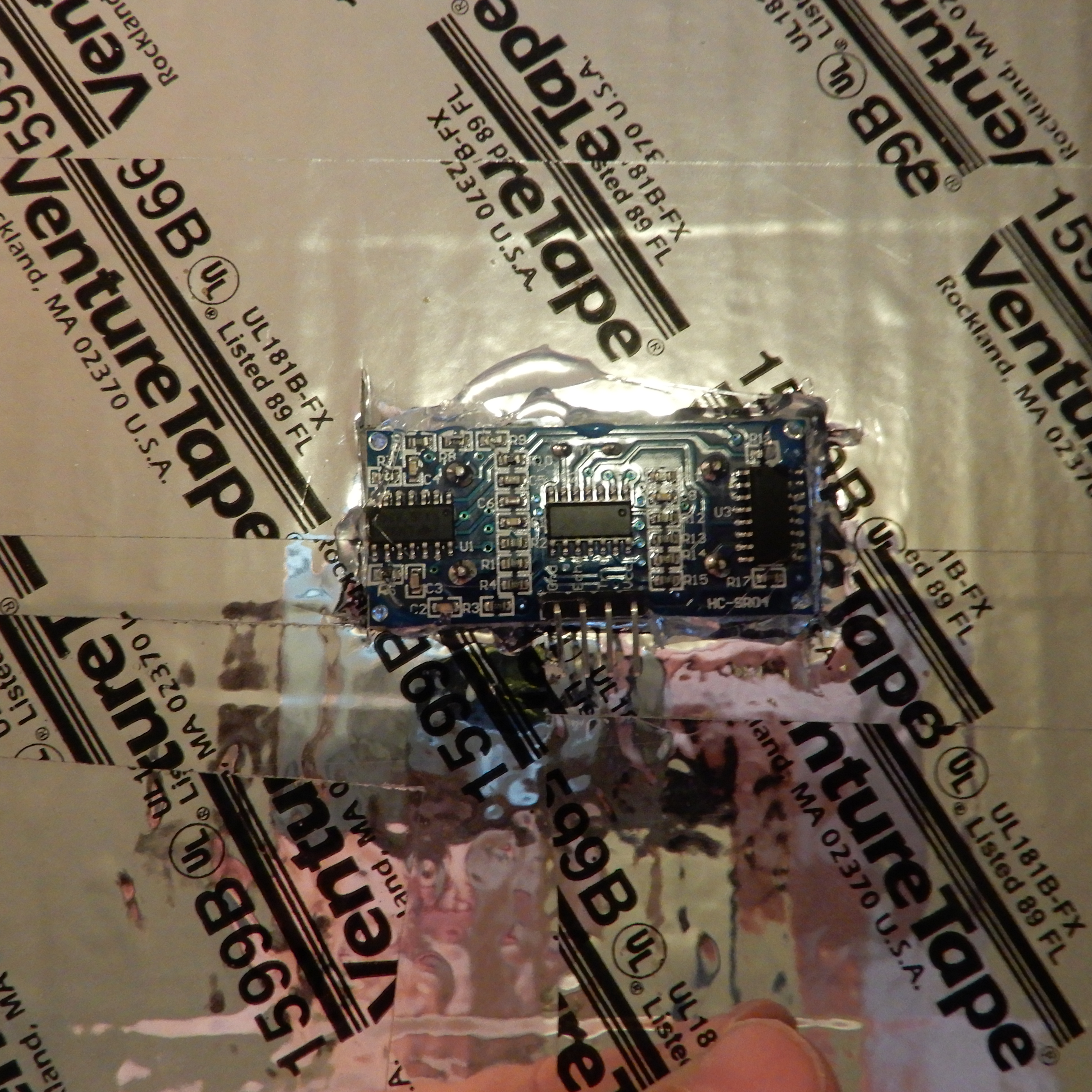
HC-SR04 ultrasonic sensor
Female to male jumper wires
A tall, long box like the one in the picture - use whatever will work for you, but try to keep it as close to the picture as possible (except the bulb vs LEDs).
Cardboard - lots of it too
Reflective Tape - you can use any kind. I'll refer to it from now on as just "tape"
1 leftover food container that is medium sized for the Arduino
1 leftover food container that is smaller for the servo equipment
A drill, or a rotary tool drill attachment
Step 1: Explanation
Here's how this device works (the lights are always on)
Step 2: Container Creation
First, prep the platform. Cut a piece of cardboard at least as long as your box, and almost as wide.
Then, cover it completely in tape. Then, cover the inside of the main container completely with tape as well. After doing that, cover the outside of the main container with white paint. For touch-ups, use a smaller paintbrush. Cut a thin, rectangular hole in the back of the main container, like the one in the picture, with your rotary tool and thread the tape covered cardboard through, but don't glue it yet.
Drill a hole in the back of the top part of the container for the cartridge servo connector.
Step 3: Arduino Container
At the end, your finished product should look like the CAD drawing above, with the front box on the top being your Arduino and the back box on the top being your servo for the cartridge. The cartridge is not shown. The first servo, the sensor, and the UV-C light will be inside the main, rectangular container. We have just made the front box, housing the Arduino.
Get your medium container and cover its outside with white paint. Then, take the lid of the container and drill a hole on one side, large enough to fit four F/M jumper wires side by side. This hole is for the ultrasonic sensor, to give you an idea of the size of the hole.
Drill a hole in the center large enough for a servo connector and 3 F/M jumper wires.
Drill a hole beside the first servo hole for the second servo connector.
Last, drill a hole in the opposite side from the ultrasonic sensor hole. This hole is for the UV-C light, whatever you may use as one.
Now, drill these same holes, except for the second servo hole, in this same alignment, on the top of the main container.
At the end, your finished product should look like the CAD drawing in Schematics, with the front box on the top being your Arduino and the back box on the top being your servo for the cartridge. The cartridge is not shown. The first servo, the sensor, and the UV-C light will be inside the main, rectangular container. We have just made the front box, housing the Arduino.
Step 4: Building the Circuit
Wait to wire it up until Step 6.
The circuit is the first picture above. I know it's a little hard to decipher, so I am writing out the connections right here:
For LEDs (if you're using them)
myservo2 (cartridge servo) = 10
Wait to wire it up until Step 6.
Step 5: Code
Step 6: Mounting the Circuit
If you still don't get it, look at the pictures.
At this stage you should have your main container painted, and covered on the inside with reflective tape.
Take your Arduino container and place the Arduino inside.
Then, thread the servo connector through both servo holes, the one on the top of the main container and the one on the Arduino container, and wire it up. Thread the ultrasonic sensor connector through its hole and wire it up.
Thread the second servo's connector through its holes, and wire it up.
And last, thread the UV-C light's connections through its holes to the Arduino and finish the job.
For clarification, the first servo, light, and sensor go on the inside of the main container and their wires thread through their respective holes in the top of the main container and the bottom (the lid) of the Arduino container.
If you still don't get it, look at the pictures.
Step 7: Mounting Your Arduino Container
Keep your CAD finished product in mind as we do this. Since your Arduino container should already be on top, (I put mine inside the main container and hung it from the ceiling, but the way that we're doing here is a better way), hot glue it down on the top. Hot glue the light in its top hole.
Step 8: Mounting the Door
The inside of the container is now done, except for the sensor mounting.
Follow the first picture here.
Stack pieces of cardboard on top of each other until they are about two inches tall, with hot glue in between each layer. After doing that, glue it to the front left side of the container, like in the picture. Glue the first servo to the other side, like in the picture.
Take a piece of cardboard and make one hole in each top corner, a total of two. Thread pieces of string through and glue them in. The string in the left hole should be a little longer than the right string. Then, glue both strings to one servo horn, so one side of the main container is supporting the door. Now experiment with the myservo numbers in the code to find a perfect lift, so that a mask can get out, then the door shuts.
The inside of the container is now done, except for the sensor mounting.
Step 9: Mounting the Cartridge
Experiment with the code at myservo2 to find the perfect lift so that a mask can slide down to the platform inside the main container when the servo lifts.
Glue servo 2 to the back like the picture. Take a cardboard box large enough to hold 20 stacked masks and make a long rectangular hole in the front. Glue a string in the hole that is long enough to reach the servo on the top. Glue a ramp in the bottom of the box and cover the rest of the bottom with cardboard. Look at the picture for reference.
Cut a rectangular hole in the back of the main container and thread the ramp through, so that a mask could get to the main platform if the servo lifted the cartridge. Glue the string in the back of the box to the servo's horn.
Experiment with the code at myservo2 to find the perfect lift so that a mask can slide down to the platform inside the main container when the servo lifts.
Mount the sensor to the front as shown in the picture.
Glue cardboard panels painted white to the front, so it looks like the finished picture. Put a white box over the servo and glue it in. This is simply for looks, so if you don't want to, you don't have to.
Make sure it looks like you want it!
After testing, glue the main platform in.
I left the box off of the servo for this picture.
Step 11: Finish