In this tutorial, I am going to show you how to read multiple analog values using only one analog input pin.
Introduction: How to Read Multiple Analog Values Using One Analog Pin
Step 1: Why You Want to This
In this tutorial, I am going to show you how to read multiple analog values using only one analog input pin.
watch this video tutorial- https://youtu.be/pFE58xj1p-c
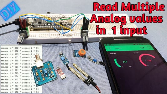
unlike other boards, nodeMCU has only one analog pin so if you want to be read more than one anlog value using nodemcu ? is it possible to read multiple analog values using only one pin.? yes
if you are an electronics enthusiast or a hobbyist you might familiar with lots of microcontroller boards like
Arduino Uno has 6 analog pin , nano has 8 pins, the pro mini has 6 pin
unlike other boards, nodeMCU has only one analog pin so if you want to be read more than one anlog value using nodemcu ? is it possible to read multiple analog values using only one pin.? yes
Step 2: How Is That Possible?
we are done this by turning on and off sensors like multiplexing .first we turn on one sensor and we read the analog data from that sensor and at the next step we turn on the next sensor and turnoff the first sensor and read data from the second sensor that it
we are done this by turning on and off sensors like multiplexing .first we turn on one sensor and we read the analog data from that sensor and at the next step we turn on the next sensor and turnoff the first sensor and read data from the second sensor that it
Step 3: Things Needed for This Project
- nodemcu or arduino
- 2*variable resistors
- 2*diodes
- breadboard
- some wires
Step 4: Circuit Diagram
connectionspositives of variable resistors to d1 and d2 grounds to grounds connect analog pins to diodes positive side connect diodes negative end to A0 of nodemcu I used diodes to overcome overlapping data that's all about connections
in this circuit diagram, you can see I connected positive terminals of variable resistors to digital pin 1 and 2 so we can turn off and on variable resistors by turning on and off the digital pins
connectionspositives of variable resistors to d1 and d2 grounds to grounds connect analog pins to diodes positive side connect diodes negative end to A0 of nodemcu I used diodes to overcome overlapping data that's all about connections
Step 5: Programming
download code and library
download code and library
Step 6: Blynk App Setup
download code and library
please watch the video for full instructions