This project describes how to design a high reliability, contactless rotary switch or encoder using GreenPAK SLG46537.
This project describes how to design a high reliability rotary switch or encoder using a GreenPAK™. This switch design is contactless, and therefore ignores contact oxidation and wear. It is ideal for use outdoors where there is long term moisture, dust, temperature extremes, etc.
The GreenPAK SLG46537: this IC provides all the circuit functions for this design. It generates a signal (EVAL) for improved signal to noise, receives inputs from each sector pad of the rotary switch, and interprets each sector pad using the Asynchronous State Machine (ASM) to guarantee only one switch selection.
Below we described steps needed to understand how the solution has been programmed to create the contactless rotary encoder. However, if you just want to get the result of programming, download GreenPAK Designer software to view the already completed GreenPAK Design file. Plug the GreenPAK Development Kit into your computer and hit the program to design the device.
Design Concept
This design works by timing. It generates a clock (EVAL) signal to slowly pull up each sector pad through external 100 kohm resistors (Figure 1). The EVAL signal is capacitively coupled to the central “wiper” which drives the rising edge of the selected sector pad faster than all the others (fast in Figure 1). The GreenPAK Asynchronous State Machine (ASM) then evaluates which rising edge arrived first and the result gets latched. The advantage of the capacitive coupling design is for reliability. Whether the encoder is built capacitive and then wears out to direct connection, or built direct connection and then degrades (oxidizes) to capacitive, it still works.
The top-level schematic in Figure 1 shows the outputs connected to external LED’s for demonstration.
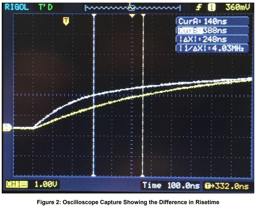
Figure 2 is an oscilloscope capture showing the difference in risetime of a sector pad having the selector wiper aligned with it, versus the risetime of the other unselected pads. The delta T is 248 nS, which more than enough margin for the GreenPAK Asynchronous State Machine (ASM) to resolve. The ASM can resolve in under a nanosecond, and its internal arbitration circuitry guarantees that only one state is valid. Hence, only one output will register at any time.
GreenPAK Design Implementation
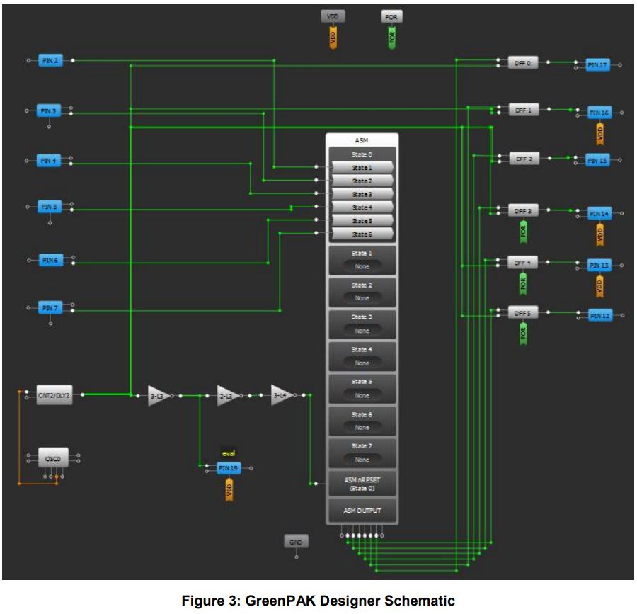
The schematic programmed into the GreenPAK IC is shown in Figure 3.
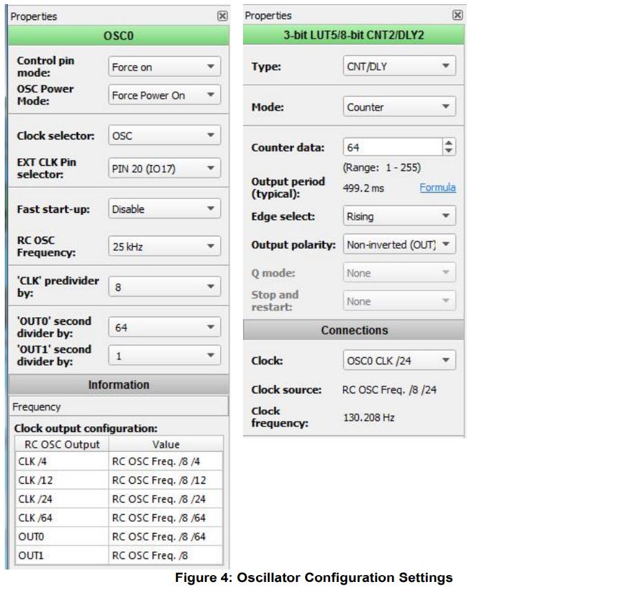
To save power, the EVAL signal is generated at a rate appropriate for the application response time. The low frequency oscillator is used and further divided down with CNT2. In this example it’s approximately 16 Hz. See configuration settings in Figure 4.
The illustration of the possible state transitions is shown in the ASM state diagram (Figure 5).
A slightly delayed copy of EVAL is used as an ASM reset with each cycle. This ensures that we always start from STATE0. After the ASM reset condition, EVAL signal is monitored by the ASM at each of the pads. Only the earliest rising edge will cause the state transition out of STATE0. Any subsequent rising edges from other pads will be ignored since only one state transition is possible. This is also because of the way we configured the ASM as shown in Figure 6. Each of the 6 ASM output states corresponds to only one of the sector pads.
The DFF latches hold the ASM result steady so that there is no switching of the final output during ASM reset. The desired polarity for driving our open drain NMOS output pins requires us to configure the DFF’s with inverted outputs.
Test Results
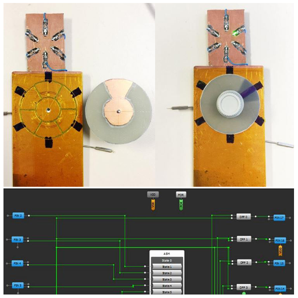
The photos below show a crude prototype, fully operational. It is also low power, measuring only 5 uA for the GreenPAK.
The layout of pads and wiper are maximized for strongest signal. The prototype was found to be immune to strong RF interference such as large fluorescent bulbs, and 5 W 145 MHz radio. This is likely because all pads receive the interference in common mode.
It is possible to lay out the pads and wiper dimensions so there is no overlap of 2 pads at the same time to the wiper in any position. This may not really be necessary since the ASM arbitration circuitry will allow only one of the states to be valid, even in the event of 2 simultaneous rising edges. That is another reason this design is robust. Good sensitivity is achieved with the board layout having interconnect traces to the pads very narrow, and equal length to each other so the total capacitance of each sector pad is matched with the others. A final product could include mechanical detents for the wiper so it “clicks” when centered to each of the positions, and also provides a nice tactile feel.
Conclusion
The GreenPAK SLG46537 IC offers a low power, robust, and complete solution for this high reliability rotary switch. It is ideal for applications such as outdoor timers and controls that require stable, long term operation.