Hi Ben.
Re your new design (the first one in your post), it looks OK.
I'd suggest adding a bias resistor from the common of the two switches (i.e. pin 5 of U2) to the virtual ground rail. 100k should be fine. This is just to stop that node from floating during the time (if there is any) when both switches are OFF during a changeover.
Also I would add a 10k resistor straight across the output connector. Without this, if you power up the circuit before you plug the amplifier into the output, you'll get a thump when you plug it in, because C9 will have 0V across it, so the voltage at the output connector will initially be 4.5V. Once you plug in the amp, it will charge up C9 to 4.5V and bring the DC voltage at the output down to zero, but while C9 is charging, the amp will see a big spike. Adding that resistor makes sure that C9 is charged up, and there is 0V DC on the output, before you plug in the amp.
I have added in R6 and C7, R7 and C8 as suggested, although I haven't had a chance to test if this helps the popping yet. It has also been suggested to me to add a RC filter by adding a resister (say 200r) in series with the supply to the 4047 and a large value cap to ground from it's supply pin. I haven't reflected this in the diagram, or testest it yet, but this should sop any noise coming from the 4047 affecting the rest of the circuit.
Yes, that might help.
So to clarify what you are saying - when there is no signal the line is sat at +4.5v with the switch sat either open or closed. As the signal is disconnected the output is then connected to +4.5v also there should be no popping because theere is no change in voltage.
Right so far.
When I start playing the voltage should increase a little, relative to how hard I'm playing. I'm unsure how much, but for the purpose of this say the pickups on the guitar are outputitng 0.5v. So the signal level is +4.5v + 0.5v = 5v, and the virtual ground is biased to +4.5v, so when the switches are toggled the level changes between +5v and +4.5v, which will pop because there is a voltage change of +/-0.5v.
Not exactly. When you're not playing, the signal at all points in the signal path is steady at the virtual ground voltage. So switching the switched node (the "output" of the switch circuit) between the audio signal and virtual ground causes no change in the voltage, and therefore no pops.
When you play, the signal at the output of the first op-amp consists of the AC waveform from your guitar, superimposed onto the virtual ground voltage. Assuming that your guitar is putting out 200 mV peak-to-peak of AC voltage, that means that signal is varying between 4.4V and 4.6V in accordance with the signal.
You've probably seen an oscilloscope trace of the signal from an electric guitar. The instantaneous voltage goes up and down in a complex way according to the frequencies present in the signal from the pickup. It has a maximum positive voltage and a maximum negative voltage, and it crosses through the centre voltage at various times.
At any moment in time, the signal at the first op-amp output is somewhere between 4.4V and 4.6V. At the time your switches change over, if that voltage happens to be far away from 4.5V (for example, around 4.6V), then the switching action will cause the voltage at the switched node to jump suddenly from 4.6V to 4.5V. This sudden jump causes a click or pop. It contains a lot of high frequencies and is quite noticeable to the ear.
Actually, it doesn't matter what the instantaneous voltage is when the switch changeover occurs. Even if the switch changeover happens to occur exactly when the signal crosses zero, and the first op-amp output is exactly 4.5V, the sudden cessation of the signal causes an audible pop.
Imagine your eardrum moving in response to the signal. When the signal is present, your eardrum moves in and out rhythmically, following the instantaneous voltage of the signal waveform. If that signal suddenly stops, the (relatively) smooth movement of your eardrum stops suddenly. Whether this change also involves a sharp drop or increase in the instantaneous voltage (as in the first case where the switches change over when the signal is at a peak), or whether the change occurs when the instantaneous voltage was crossing zero and the signal simply suddenly stops changing, the smooth cyclic movement of the eardrum is interrupted with a bang, and that's what you hear.
The only way to eliminate the audible pop is to reduce the signal amplitude more gradually. The more gradually you reduce it, the less offensive the sound will be. Of course if you reduce it too gradually, it won't sound like a sudden stop and start any more. So you have to compromise.
This is quieter than when the signal was being shunted to ground because that would have been a 5v change. If I have understood correctly this makes a lot of sense!
I'm not sure what you mean. Definitely, a sudden 4.5V change (as in your previous design) will make a much louder pop than a smaller change.
So if I also understand your answer about slowing down the change, the caps C7 and C8 are charging when the signal is high, and discharging when the signal goes low. The rate at which they discharge affects the speed at which the switch changes, as the voltage change is more gradual. By using a bigger cap it would take longer to discharge, increasing the time the switches take to open and close. At an extreme I may have to lower the maximum frequency as there is a cross over point where the switches would both be always on as the caps would take so long to discharge to a point the on/off signal changes the logic level that it would be reset by the time it's state had changed again. Basically I need to have a trapeziodal waveform rather than a hard square wave.
That's a pretty good description.
Actually I'm not sure whether the 4066 will respond to intermediate voltages by "partly" opening and closing its switches. It IS a logic IC and it's not supposed to have a (relatively) slowly changing voltage on its control inputs.
I don't think you need to worry about overlap between the switches. It does no harm if they are both partly (or even fully) on simultaneously for a short time on each changeover.
A trapezoidal control waveform is probably not ideal. I can't actually tell you what is the best envelope shape to minimise the audible pop, because I don't have that level of mathematics. Other people on the forum may be able to say.
I think the best way to do what you want is to use a variable gain amplifier instead of a CD4066. This is an amplifier whose gain is controlled by a control signal. You can do your resistor-capacitor smoothing on the control signal and the gain will vary smoothly in response, unlike the 4066, which is supposed to be controlled by a digital signal.
There are various ways of implementing a variable gain amplifier - do some googling. The LM13700 operational transconductance amplifier is a good option.
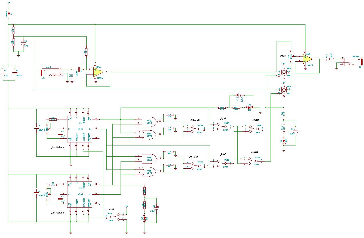
I have also included a circuit (haven't added in those new changes) which shows how I propose to use what I'm designing here. Any comments on that are much appreciated. I think this has me punching above my weight a bit, but it is pretty interesting stuff from a learning point of view!
I see the general idea, but I'm not sure you need all those options. Specifically, I think that using A OR B with Invert will be equivalent to using A AND B without Invert (assuming both oscillators have 50% duty cycle), and there's no point inverting a single control signal, so the Invert switch isn't needed. Also I would use a 3-way switch to choose between A AND B, A, and A OR B, instead of two 2-way switches.
But I think you should concentrate on getting the signal control working properly first. With a variable gain amplifier, you only need to switch one control signal, so that simplifies your switches.


")
