I see a few issues:
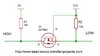
- The servo requires 4.8 V to 6 V power supply. Diode D6 will drop > 0.3 V from the 5 V supply, thus leaving less than 4.8 V for the servo. Replace D6 by a direct connection.
- The control input typically expects a 5 V PWM signal. While Q5 will deliver > +4.5 V for the high level (less than 5 V due to D2), there is no path to ground to supply 0 V to the control input. You'll need to add a push-pull driver stage here.
- " I'm testing signal coming from T2" There is no T2 in the schematic shown. Do you mean Q5? If so, where on Q5 (S, D G)?
- A strong 3.3 V signal from the CPU should be good enough to drive the control input of the servo directly without the need for an intermediate stage (T1, Q2). If you need to use a level shifter, here are a few circuits of differing complexity. A single stage driver is sufficient. You can undo the polarity inversion of a single stage driver in software.
- The diodes around the servo are imho useless. The electronics within the servo has built-in protection from reverse voltaeg spikes of the motor. It is much mor euseful to add a small LC filter into the power supply (G, +5V) of the servo:
- add a capacitor (10 µF) in parallel to the servos' supply.
- add a ferrite bead (something like this) in series with the positive supply of the servo. Do not place a ferrite in the ground path!
Hi Harald,
thank you for response. I need adjust few items from my statement, apologies if this cause confusion:
1, I'm driving little higher voltage (5.6V) so it is overcome forward voltage of diode. I will remove D6
2, So I have 5V in signal, R15 is acting as pull down , maybe I was suppose to put in front of diode?
3, You are correct T2 is Q5, +5V is connecting to S, D2 to D and G is fed by signal from T1
4, Never thought about Level shifter, good idea, as plan B I thought about Optocoupler fed by N-MOSFET due to current consumption.
5. I added diodes to due to spike I was geting from servo, I tried connect it to Arduino Uno directly (running on 5v) , the same issue and also to servo tester. Tester was was good for few turns, after that similar situation with interference, although on much smaller scale. I tried another 2 servos from the same kind, the same situation. I will try to add there RC filter, ferrite bead I will try to get hand on it (not available in local store). I', attaching screenshots from osciloscope. I will let you know how it looks like after changes (-diodes, +RC filter). Btw what values you recommend for R and C? thx