Megaditto's on K.E.'s comment.
You GOTS ! to be some kind of FEWL! if you done gones and wint trubbleshewting with a wire jumper, to then be probing places on that circuit board !
***
If your unit is one of the units shown below, you are dealing with the further TOTAL loss of functionality of a of a $100 + unit .
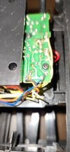
You chose one of the terminals of the motor that feeds the gear train which cycles the ball transport arm for a cycle of a minute ball drop.
Either, it is going to be having one motor terminal grounded and the other other terminal receiving 4.5-6 VDC for the duration of a minute ball transport cycle .
OR . . . .it will have a constant 6 VDC going to one motor terminal and the other terminal getting switched to
ground for an operational cycle.
Now if it happens to be wired in the last manner . . . and the unit is being powered by 4 C cells you will be having full 6 volts at a 5-7 Amp power burst level . . . on one of the motor terminals OR just about the same at the other terminal , less the loss of the LOW resistance of a motor winding .
Further referring back to
*** and if you happen to use that jumper wire to touch the base connection of one of the transistors on the board in the correct polarity.
PFFFFFFFFFFFFFTTTTTTTTT ! ! ! ! GAME OVER . . . as its junction totally vaporizes.
What you want to do is be using a meter in its DC voltage reading mode to see how that motor is being powered.
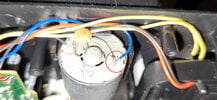
Now check and see if any and or all of those transistors have identifier markings on them ? Feed them back by my preassigned color codes.
From what your pics will let me make out, here is my perceived . . . .
MOW-DIE . . . OP-ER-AND-I . . . mus-es-es-es-es . . . . . and
BASIC CONCEPT OF DESIGN. . . . . .
USE THESE HOT LINKS for INITIAL PRODUCT FAMILIARIZATION REFERENCING . . . .
Ball Clock . . . . illustrations proper
Ball Clock Video of actual cycle time of ball loading
Find many great new & used options and get the best deals for Can You Imagine Time Machine Rolling Ball Bearing Tabletop Clock Battery Powered at the best online prices at eBay! Free shipping for many products!
www.ebay.com
View attachment 56551
YOUR PHOTOS MARKED UP FOR REFERENCING . . . .
Fo' Mo' Biggah Pick-choors
Each one above has a different seconds display wheel . . . . one is only visible from the top downwards while the other will let you see it as a front on display . . . . . now, which one is being your units display mode.
( On one of your units pics, I can see some side numbering. . . . . but it might . . ALSO be frontally marked. )
With the help of your last two photos . . . . let me give my thought on the operation of the unit . . . you then feedback any discreptancies.
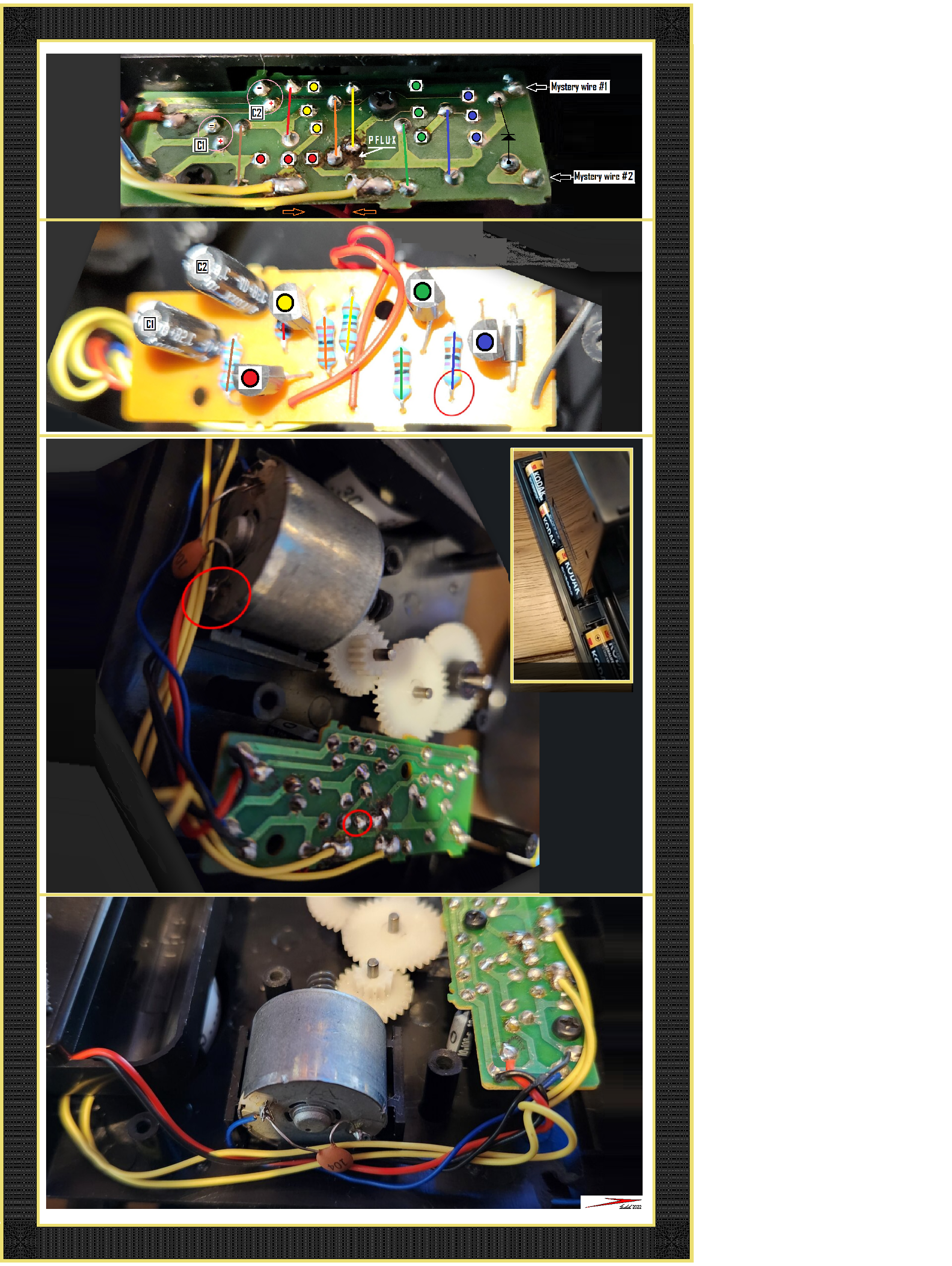
There is a basic quartz clock movement in the black housed portion that has a 60 second drum / disc display.
There are two heavier RED and BLACK wires that feed 1.5 VDC power into the basic clock movement . . that then runs the clock continually. Those incoming power wires terminate at the pcb's gear motors corner and then travel upwards as 2 foil routes .
The RED connection travels to the + of E-cap C2 for some filtering and then further down to the Collector ? Emitter ? of the BLUE transistor on the board .
The BLACK connection travels initially to the - of C2 E-cap for filtering return and additionally, that foil buss path . . . all the further length of the board is being ground reference for any future DC metering needed to be done.
I can see that one transistor ( YELLOW) has side markings, so pass on the numbers of all 4 ,so that further circuit in depth analysis can be completed.
That time drum should be ticking off its 1 seconds continually.
Associated with that drum should be a bar / rod magnet mounted to it, and it should swing its magnetic field into coincidence with a companion magnetic reed switch mounted, so that a switch closure is being made at the displayed "0 seconds " time mark.
The magnetic switch wiring exits the quartz clock housing as being the two smaller yellow wires which go to the circuit boards side / central area as two connections to the foils at the area just below YOUR marked in RED circle.
Now the solder job on the left wire to the Pee Cee Bee is nothing to confess as having done, but then, the one to the right is AAA-TRROO-SHUSH, instead of a being profession solder reflow joint it looks like a melted and then "
drip soldered " joint.
In addition, it has a top formed extended solder "horn" loop, it's looking PWECAWIOUSLY close to one of the RED transistors adjunct foil.
Cleanse all of the board excess " Pflux" residue off in that area and then resolder both joints . . . . .PROFESSIONALLY.
Until I get further future info coming forward, I am initially seeing a " Zero" seconds timer drums magnet shorting this reed relays orange wires together and getting drive voltage from GREEN line resistor to initially base bias RED transistor on. Its conduction revs up the motor and the gear train starts rotating the arm that then repositions a minute ball.
I am seeing a second pair of wires on the component side of the board which seem to tie into the identical connection points as the previous yellow set.
I want to think that they are routing towards a second switch.
Think of that arm that rotates to position the ball and its BOTTOM END HALF, and see if there is not a magnet on it . With congruent consideration of that magnet being within " magnetic field provimity" of another mag reed swittch which it activates.
This switch variant is being a normally closed switch.
This is accomplished by a proper strength biasing magnet, epoxy affixed to the reed switch. It normally is marginally strong enough to just reliably close the reed switch . . . . .continually . . . . .. thus it is having a normally closed spst switch action .
PERCEIVED OPERATIONAL RUNDOWN . . . .
The clock is running with the seconds ever advancing, meanwhile . . . .
BACK IN THE JUNGLE ##### . . . the ball moving claw is in its dormant position, with ball claw at top and its magnet / loaded opposite end at bottom position and having its magnetic field opposing the field of the reed switches biasing magnet and cancelling out the holding closed reed switch. That results in an open circuit reed switch presently.
A BALL DROP CYCLE . . . . minute
As the time clock reaches O seconds, that reed switch within the clock housing closes from magnetic field proximity.
That then switches the motor on and its gear train driven pendulum starts moving, and instantly the magnet in the pendulum bottom, has lost its overriding effect on the reed switches bias magnet. Now instead of being in the open circuit condition, it is now closed circuit and shunting, and providing the same motor run action that the clocks reed switch was initially providing. THAT IS . . .UNTIL . . . the arm has moved its ball and completed a 1 turn revolution where that pendulum bottom magnet then de activates that reed switch again, stops the motor . . .screeeeeeech .
Then Its waiting . . . . until the seconds timer hits "0" again, for a cycle repeat..
Referencing the "C" battery installation . . . . . INSET
Is your setup of the cells, being the same as this ?
Note how the single one cell at the bottom is spaced apart.
So o o o o o o . . . we know that it is using 1.5 VDC for the clock . . . .BUT is the motor then running from 4.5 VDC or is 6 VDC used for the motor ?
I can see a critical battery life / time keeping fault, if being the latter.
ADD ON . . . after just seeing your power wall wart last picture.
If your unit is being one of the two shown, they have a mini power plug for AC line operation from a wall wart.
To evaluate YOUR wall wart unit used, can you test its output voltage at the chassis when the ball arm is immobile and also when the motor is loading down the unit ?
I also need to know where / and / what the two small
Mystery 1 &2 gray or black wires at the end of the board connect to .
Reviewing K.E.'s 2nd comment . . .
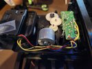
I'm guessing that the circuit board is a simple mono-stable circuit
Circuit wise, I pinpointed the two 100 ufd E -caps functions as being used as shunting / filter caps on the 2 supply voltages being used .
So from the " mono-stable aspect " we needs a Capacitive time constant complementing a R value . . .
SHOW ME THE MONEY (CAPACITANCE) !. . . of the boards remaining discrete components.
Plus that pendulum always comes to rest . . .stopping on a dime . . . every time , positionally.
##### . . . . . . . . Back in time . . . . . SOUND BITE . . . . . .
Thaaaaaaaasssssit . . . . .
73's de Edd . . . . .
FACTOID ?
Ye Olde Ainglish Houses had thatched roofs-thick straw-piled high, with no wood underneath. It was the only place for animals to get warm, so all the cats and other small animals (mice, bugs) lived in the roof. When it rained it became slippery and sometimes the animals would slip and fall off the roof...
Hence the saying "It's raining cats and dogs."
.