


Project Log
So I needed my power meter. It's a cheap Chinese meter that was thrown in with an order from an electronics component retailer here. It's a "CIXI YIDONG ELECTRONIC CO., LTD." branded device also labelled as "Type: EMA-1 V07442". I guess that might mean something to someone who Googles for it.
I noted that the batteries were flat, so I replaced them (2 x LR44). When I plugged it in my mains voltage measured 134V. Aha, I think. That's why I'm having problems! Well it turns out that the mains voltage is fine and the meter is giving spurious readings.
Oh, and apologies for the photos in advance. I took them in the workshop, and it's not the best lit place in the world.
.JPG")
Now it's time to try to repair it!
There's two screws on the back -- no need to remove the battery cover. After these are removed a little judicious work with a large screwdriver easily unpops the plastic clips and we're in!
.JPG")
There's not a lot to it. I imagine a lot happens under that epoxy blob though!
Basically the rear board contains a power supply and the current/voltage sensing connections. All these are passed t the main board where the magic happens.
Could it be something obvious?
.JPG")
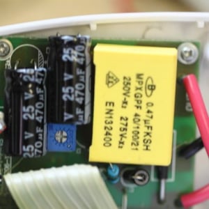
Oh, it couldn't be that easy could it? That capacitor on the right looks like it has expired, and the one on the left doesn't look too flash either.
Actually, I didn't notice the bulge at the bottom of the left capacitor until I saw this photo. I had already decided to replace both of them.
.JPG")
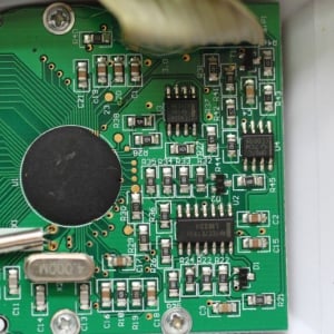
Here's the main board. Full of common parts too. SO if something has happened to the input stage, there's a good chance I can replace parts here too.
.JPG")
Here's the back of the power supply board. There's obviously more going on here than just a power supply.
Note that it doesn't look like it was well cleaned after manufacture.
The capacitors have been straightened up and you can see their leads under diodes D2 and D3 on the top left corner.
.JPG") I guess this shows I can desolder.
I guess this shows I can desolder.
Hmmm "431" on the SOT-23 device. Could that be an LM431? (My datasheets suggest not)
.JPG")
The replacement caps are 470uF 25V 105C low ESR caps. The originals claim to be 470uF 16V 105C. I've heard of Fujicon, has anyone heard of ZhongTai? (Google tells me that ZhongTai means "peace and safety for the people")
Anyway, the replacements are a lot bigger, but I can make them fit...
.JPG")
It's not easy to see here, but the new caps are no higher in profile than the yellow 0.47uF cap sitting beside them.
So now for the bang test (It passed).
And then to see if I get a more reasonable reading
.JPG")
I'm going to call that close enough.
It is interesting to see the range of variation in mains voltage. I was seeing between 247 and 250, and after I got this working It read 251 on another power point (probably another phase).
Given that my state used to have 250VAC officially before changing it to 240VAC, and then either 220VAC or 230VAC (depending on who you talk to), I can hardly say I'm surprised. All of these lower voltage standards allow for variations which (surprise) mean that my 251V is within spec, albeit at the upper end.
I noted that the batteries were flat, so I replaced them (2 x LR44). When I plugged it in my mains voltage measured 134V. Aha, I think. That's why I'm having problems! Well it turns out that the mains voltage is fine and the meter is giving spurious readings.
Oh, and apologies for the photos in advance. I took them in the workshop, and it's not the best lit place in the world.
Now it's time to try to repair it!
There's two screws on the back -- no need to remove the battery cover. After these are removed a little judicious work with a large screwdriver easily unpops the plastic clips and we're in!
There's not a lot to it. I imagine a lot happens under that epoxy blob though!
Basically the rear board contains a power supply and the current/voltage sensing connections. All these are passed t the main board where the magic happens.
Could it be something obvious?
Oh, it couldn't be that easy could it? That capacitor on the right looks like it has expired, and the one on the left doesn't look too flash either.
Actually, I didn't notice the bulge at the bottom of the left capacitor until I saw this photo. I had already decided to replace both of them.
Here's the main board. Full of common parts too. SO if something has happened to the input stage, there's a good chance I can replace parts here too.
Here's the back of the power supply board. There's obviously more going on here than just a power supply.
Note that it doesn't look like it was well cleaned after manufacture.
The capacitors have been straightened up and you can see their leads under diodes D2 and D3 on the top left corner.
Hmmm "431" on the SOT-23 device. Could that be an LM431? (My datasheets suggest not)
The replacement caps are 470uF 25V 105C low ESR caps. The originals claim to be 470uF 16V 105C. I've heard of Fujicon, has anyone heard of ZhongTai? (Google tells me that ZhongTai means "peace and safety for the people")
Anyway, the replacements are a lot bigger, but I can make them fit...
It's not easy to see here, but the new caps are no higher in profile than the yellow 0.47uF cap sitting beside them.
So now for the bang test (It passed).
And then to see if I get a more reasonable reading
I'm going to call that close enough.
It is interesting to see the range of variation in mains voltage. I was seeing between 247 and 250, and after I got this working It read 251 on another power point (probably another phase).
Given that my state used to have 250VAC officially before changing it to 240VAC, and then either 220VAC or 230VAC (depending on who you talk to), I can hardly say I'm surprised. All of these lower voltage standards allow for variations which (surprise) mean that my 251V is within spec, albeit at the upper end.
