Maker Pro
Maker Pro

0-60VDC POWER SUPPLY CONTROLLED BY 0-5VDC

chuzkin

Apr 22, 2014
3
Joined
Apr 22, 2014
Messages
3
Hi friends.

I think i should give more detailed information.
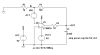
What I need is to uso a PIC microcontroller, so using 2 push-buttons, I can increase / decrease the voltage level from 0VDC to 60VDC. The PIC output range is 0-5VDC, so I need an interface to convert this signal to 0-60VDC.
Current output needed 2.5 or 3A. Load is a magnet, with the following voltage/current measured:

40V - 2.08A
34.8V - 1.85A
30.3V - 1.26A
24.5V - 0.69A
18.4V - 0.12A
17V - 0.01A

The idea is to replace actual boards to get 50 or 60VDC in order to achieve a stronger magnetic force.


Thanks!

Best regards.
 

(*steve*)

¡sǝpodᴉʇuɐ ǝɥʇ ɹɐǝɥd
Moderator
Jan 21, 2010
25,510
Joined
Jan 21, 2010
Messages
25,510
The simple answer is that you change the feedback circuit of the power supply so that you compare the output voltage divided by 12 with the analogue output of the PIC. The result of this comparison is used to control the switching or pass element of the regulator.

This means that if the output of the PIC is 1V, you get 12V from the power supply. Note that you will probably need to filter the output of the PIC as it is almost certainly generated by PWM and will be quite noisy.

Do you have a design in mind for the rest of the power supply?
 

chuzkin

Apr 22, 2014
3
Joined
Apr 22, 2014
Messages
3
I do not have an idea, and that is the reason for this post.

Greetings.
 

(*steve*)

¡sǝpodᴉʇuɐ ǝɥʇ ɹɐǝɥd
Moderator
Jan 21, 2010
25,510
Joined
Jan 21, 2010
Messages
25,510
How much experience do you have with electronics?

A 180W power supply is going to pose some significant issues, especially in regard to heat.

Switchmode supplies are simpler in this respect, but in other respects are more complex.

And how much experience do you have with PICs? You might be able to offload some complexity to it.
 

chuzkin

Apr 22, 2014
3
Joined
Apr 22, 2014
Messages
3
I know how to program PICs. I already developed some applications including analog to digital conversion and processing and build a tachometer.
What do you suggest for this kind of power supply? Any idea or schematic?

Best regards.
 

(*steve*)

¡sǝpodᴉʇuɐ ǝɥʇ ɹɐǝɥd
Moderator
Jan 21, 2010
25,510
Joined
Jan 21, 2010
Messages
25,510
Here is a conceptual design.

Vreg Concept.png

In this example the output voltage is (Vref * (R2 + R3)) / R3.

You would choose R2 and R3 so that they add up to about 10k, and so that R2 is about 12 times larger than R3. Thus the output voltage will be Vref * 13. In theory this allows Vref changing from 0 to 5V to correspond to an output voltage between 0 and 65V.

In practice this has lots of problems. I'll fix them up in the next design, but you need to be aware of some I *won't* fix.

1) Q1 has a high power dissipation, especially at lower voltages and higher currents
2) The output may not be very stable below a couple of volts.
3) There is no current limiting
 

(*steve*)

¡sǝpodᴉʇuɐ ǝɥʇ ɹɐǝɥd
Moderator
Jan 21, 2010
25,510
Joined
Jan 21, 2010
Messages
25,510
Here is a more practical design. Note that the transistors shown will not be appropriate for the voltages you're interested in.

Vreg Better.png

The main issues here are the VCEO of the three transistors.

Note that R4/R5 will limit the practical minimum voltage to about ((Vin * R5) / (R4 + R5)) + 1 volts (for a 70V input, that's around 4V -- not significant in this case since you want a 17V minimum)

For a 70V input voltage, you get the following:

Input VoltageVrefOutput VoltageOutput CurrentQ1 power dissipation
70 V1.31 V17.0 V0.1 A5.3 W
70 V1.42 V18.5 V0.12 A6.2 W
70 V1.88 V24.4 V0.69 A31.5 W
70 V2.33 V30.3 V1.25 A50.0 W
70 V2.68 V34.8 V1.85 A65.1 W
70 V3.08 V40.0 V2.08 A62.4 W
70 V3.85 V50.0 V2.50 A50.0 W
70 V5 V65.0 V3 A15.0 W
Luckily you don't want high currents at low voltages or the figures would be much worse. Even so, 65W dissipation will require a fairly massive heatsink (I'd be looking for 1 degC/W or better).

I haven't dealt with practical aspects of the reference voltage or with the type and power supply of the op-amp, I'll let you think about this first.
 

KrisBlueNZ

Sadly passed away in 2015
Nov 28, 2011
8,393
Joined
Nov 28, 2011
Messages
8,393
Steve, wouldn't there be a stability problem with two common emitter stages inside the feedback loop? I don't really understand how to calculate stability but my gut feeling based on prior experience is that the extra gain and delay introduced by even a single common emitter stage inside an op-amp feedback loop will cause instability. Or more honestly, wild oscillation! What do you think?
 

(*steve*)

¡sǝpodᴉʇuɐ ǝɥʇ ɹɐǝɥd
Moderator
Jan 21, 2010
25,510
Joined
Jan 21, 2010
Messages
25,510
Steve, wouldn't there be a stability problem with two common emitter stages inside the feedback loop?

Sure would. But it's not so much the extra gain as the additional phase shift -- or possibly an increase in the gain bandwidth that will allow oscillation at higher frequencies.

I was thinking about that and was going to make some changes.

I don't really understand how to calculate stability but my gut feeling based on prior experience is that the extra gain and delay introduced by even a single common emitter stage inside an op-amp feedback loop will cause instability. Or more honestly, wild oscillation! What do you think?

Either or both! The trick is to gain some margin.

Given that the load is inductive, a small change in current through Q1 is going to cause a disproportionate change in voltage.

The first thing to do is to add some capacitance to the output, the second thing may be to add a smaller capacitance from the base of Q1 to ground.
 

KrisBlueNZ

Sadly passed away in 2015
Nov 28, 2011
8,393
Joined
Nov 28, 2011
Messages
8,393
Given that the load is inductive, a small change in current through Q1 is going to cause a disproportionate change in voltage.
Oh, that's even worse!
The first thing to do is to add some capacitance to the output, the second thing may be to add a smaller capacitance from the base of Q1 to ground.
Really? I would have thought both of those things would increase the delay. From what I've seen, this problem is normally handled by adding a fast negative feedback path using a capacitor from the op-amp output to the inverting input, which slows the op-amp down.

Another idea I had would be to add emitter degeneration resistors on Q1 and Q2. But I think the best answer could be a high-voltage op-amp. I have no experience with these, but I searched Digikey and found some options:

Linear Technology LTC2057HV http://www.digikey.com/product-detail/en/LTC2057HVIMS8#PBF/LTC2057HVIMS8#PBF-ND/4156546 USD 5.
60V max supply. Chopper-stabilised HV op-amp. SMT only.

Texas Instruments OPA445 http://www.digikey.com/product-detail/en/OPA445AP/OPA445AP-ND/272050 USD 12.
90V max supply. Available in DIP-8. Output only swings to within 5V of each rail.

Texas Instruments OPA452 http://www.digikey.com/product-detail/en/OPA452TA-1/OPA452TA-1-ND/362296 USD 7.
Texas Instruments OPA453 http://www.digikey.com/product-detail/en/OPA453TA-1/OPA453TA-1-ND/362299 USD 7.
80V max supply. Output swings to within 1V of each rail. "Low cost". TO220-7 package. 50 mA output drive. 452 is optimised for unity gain; 453 for gains of 5 and higher.

Texas Instruments OPA454 http://www.digikey.com/product-detail/en/OPA454AIDDA/296-22997-5-ND/1770310 USD 8.
100V max supply. Output swings to within 1V of each rail. "Low cost". SO-8 package with heatsink pad. 50 mA output drive. This seems like a very good option to me.

Texas Instruments OPA544 http://www.digikey.com/product-detail/en/OPA544T/OPA544T-ND/251158 USD 18.
70V max supply. Output only swings to within 5V of each rail. Output current 2A peak! TO220-5. One suggested application is "Programmable power supply".

Texas Instruments OPA541 http://www.digikey.com/product-detail/en/OPA541AP/OPA541AP-ND/251157 (11-pin SIP with heatsink tab; USD 22) and http://www.digikey.com/product-detail/en/OPA541BM/296-36065-5-ND/301304 (8-pin TO-3; USD 140).
80V max supply. Output only swings to within 5V of each rail. Output current up to 10A peak! Current limiting with external resistor. One suggested application is "Programmable power supply". With this one, the circuit would almost design itself!

In the process I also found some high-side current sense amplifiers that could be useful for current limiting:
Texas Instruments LMP8480,1
Linear Technology LTC6101HV, LT6102HV
Maxim MAX4080,1
 

Arouse1973

Adam
Dec 18, 2013
5,178
Joined
Dec 18, 2013
Messages
5,178
I wouldn't want to add any capacitance but the propogation delay for the loop is going to be quite small. I think you will still have a reasonable phase margin. I'll have a look later. I bet I am wrong again :) you could add some resistance to the vref input to give the output chance to catch up. That's the easiest thing to do.
Cheers
Adam
 

(*steve*)

¡sǝpodᴉʇuɐ ǝɥʇ ɹɐǝɥd
Moderator
Jan 21, 2010
25,510
Joined
Jan 21, 2010
Messages
25,510
I wouldn't want to add any capacitance but the propogation delay for the loop is going to be quite small. I think you will still have a reasonable phase margin. I'll have a look later. I bet I am wrong again :)

Do the calculations and tell me :)

you could add some resistance to the vref input to give the output chance to catch up. That's the easiest thing to do.

If the OP gets back to us, the source of VRef is the next issue.
 

Arouse1973

Adam
Dec 18, 2013
5,178
Joined
Dec 18, 2013
Messages
5,178
Right I have done a couple of simulations to see how the phase margin was effected but a time delay in the output loop. What I did was simulate the original circuit minus the opamp and find the time difference between the two which turned out to be about 2us. Then run a open loop simulation with a 1K and 2nF on the output and connected the feedback to that node.

First picture is schematic
Second picture is phase margin with a basic LT1001
Third picture is phase margin with a much faster LT6235

As you can see why a faster opamp is not a good idea with a 3 degree phase margin, increasing the gain would also help here. But the LT1001 has much better phase margin at 54 degrees. I found it easier to do the simulation rather than workout the poles and zeros and then calculate phase margin from that, would have taken me too long. I might have a go this week just for fun.

Adam
 

Attachments

  • AMPSTAB.PNG
    AMPSTAB.PNG
    7.7 KB · Views: 244
  • PHASELT1001.PNG
    PHASELT1001.PNG
    23.9 KB · Views: 207
  • PHASELT6235.PNG
    PHASELT6235.PNG
    24.8 KB · Views: 182

(*steve*)

¡sǝpodᴉʇuɐ ǝɥʇ ɹɐǝɥd
Moderator
Jan 21, 2010
25,510
Joined
Jan 21, 2010
Messages
25,510
Right I have done a couple of simulations to see how the phase margin was effected but a time delay in the output loop.

[...]

I found it easier to do the simulation rather than workout the poles and zeros and then calculate phase margin from that, would have taken me too long. I might have a go this week just for fun.

It would be very useful if you could start a new thread and describe the procedure you went through to do this and the software you used.

You could also document the mathematical approach.

I would find both very interesting and the process may well be useful to others as well.
 

Arouse1973

Adam
Dec 18, 2013
5,178
Joined
Dec 18, 2013
Messages
5,178
Ok I will work on a new thread this week in the evenings and see if I can get something useful together. Give me a bit of time as I am at work this week.
Cheers
Adam
 
Top