Maker Pro
Maker Pro

12 / 24 or 48v to 400V Boost Converter to charge electric car from solar panels

tantric

Mar 8, 2020
7
Joined
Mar 8, 2020
Messages
7
hi guys, goes as follows...

i have 4 x 150watt solar panels (600watts) each of 16v and 8,41 Ampere max (those at best conditions, but i can expect 400/500watts)

and i need a circuit (at least 90% efficiency) to charge the 16kW battery of my electric car with the solar panels,
the battery is 330v @ 50Ah with 400v charging voltage, i only need 400v @ 1Amp or 1.5 Amp at the output (400 / 500 Watt)
(50Ah / 1A = 50 Hours needed to charge from completely empty to full)

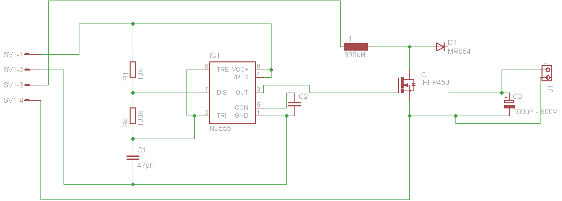
i found this schematic that will boost 12v to 400v, but the IRF450 only can handle with 15Amps,
so im thinking in using 2 sets of 2 panels in series, and those 2 sets then connected in parallel to have around 24/32v 15Ampere input

what modification do i need to do to this circuit so it can provide stable 400 v at the output,
independent of the load and independent of input voltage (since the panels vary voltage from 12 to 16 depending on the current amps demand)

i suppose i need a voltage divider from the output diode to the 555 chip, but not sure where to connect i

boost_sch.png
 

Bluejets

Oct 5, 2014
6,920
Joined
Oct 5, 2014
Messages
6,920
but the IRF450 only can handle with 15Amps,

No problem paralleling mosfets as they do not have the same parallelling problems as transistors which need ballast resistors.
So to summarise, simply add more mosfets in parallel.
 

tantric

Mar 8, 2020
7
Joined
Mar 8, 2020
Messages
7
No problem paralleling mosfets as they do not have the same parallelling problems as transistors which need ballast resistors.
So to summarise, simply add more mosfets in parallel.

cool much grateful bro

and about my question? what modification do i need to do to this circuit so it can provide stable 400 v at the output,
independent of the load and independent of input voltage (since the panels vary voltage from 12 to 16 depending on the current amps demand) , i suppose i need a voltage divider from the output diode to the 555 chip, but not sure where to connect i
 

Bluejets

Oct 5, 2014
6,920
Joined
Oct 5, 2014
Messages
6,920
Not in to designing boost converters.
Tend to leave that to the manufacturers.
Several reasons including cost and time.
 

Hunter64

Nov 20, 2018
51
Joined
Nov 20, 2018
Messages
51
Using a timer-ic for a voltage-converter like this is waiting for problems to happen. Please, search for a serious power-converter and read some datasheets and application notes before making smoke and sparks.
 

tantric

Mar 8, 2020
7
Joined
Mar 8, 2020
Messages
7
Using a timer-ic for a voltage-converter like this is waiting for problems to happen. Please, search for a serious power-converter and read some datasheets and application notes before making smoke and sparks.

okey, will look for another solution, much grateful
 

WHONOES

May 20, 2017
1,217
Joined
May 20, 2017
Messages
1,217
If you are going to have a play with this idea, I would transformer couple the output .
I have used the 555 for similar circuits and it works quite well. Its control pin can be used to provide feedback to control the O/P volts by altering the PWM mark space.
 

tantric

Mar 8, 2020
7
Joined
Mar 8, 2020
Messages
7
If you are going to have a play with this idea, I would transformer couple the output .
I have used the 555 for similar circuits and it works quite well. Its control pin can be used to provide feedback to control the O/P volts by altering the PWM mark space.

COOL, can you please provide a schematic brother? king regards
 

WHONOES

May 20, 2017
1,217
Joined
May 20, 2017
Messages
1,217
Hi. Sorry about the short delay. I had to rummage through a large number of simulations to find the attached circuit for an 800V generator showing the basics.
 

Attachments

  • 555 HT GENERATOR.pdf
    14.5 KB · Views: 23

tantric

Mar 8, 2020
7
Joined
Mar 8, 2020
Messages
7
Hi. Sorry about the short delay. I had to rummage through a large number of simulations to find the attached circuit for an 800V generator showing the basics.

i just need 400volts output... can you give me more specifications on the transformer?
 

tantric

Mar 8, 2020
7
Joined
Mar 8, 2020
Messages
7
Hi. Sorry about the short delay. I had to rummage through a large number of simulations to find the attached circuit for an 800V generator showing the basics.

what modification i have to do on this circuit to output only 400vols?
 

Alec_t

Jul 7, 2015
3,590
Joined
Jul 7, 2015
Messages
3,590
What type of battery? Lead-acid, lithium, ......? Batteries generally need a type-dependent specific charging profile to charge them safely and efficiently. Just applying a fixed 400V to them is not ideal and could be dangerous.
 

tantric

Mar 8, 2020
7
Joined
Mar 8, 2020
Messages
7
What type of battery? Lead-acid, lithium, ......? Batteries generally need a type-dependent specific charging profile to charge them safely and efficiently. Just applying a fixed 400V to them is not ideal and could be dangerous.

lithium battery's... they already have built in protection circuit for over voltage... since they can be charged with 400 v half hour fast charge
 

WHONOES

May 20, 2017
1,217
Joined
May 20, 2017
Messages
1,217
lithium battery's... they already have built in protection circuit for over voltage... since they can be charged with 400 v half hour fast charge
Alec T is correct. You will need to profile the charge regime. Just pumping current into a set of batteries is not safe. But, presumably if you are as you say, charging batteries in your car, the charging circuits contained therein will take care of the charge profile.
Designing a switch mode transformer is no mean feat. The one in my simulation is quite small and was not intended to produce a lot of current. I suggest you have a good read of the document in the link below and go from there.
You could conceivably use the buck converter system proposed in your first post and apply the control functions shown in my simulation but, this would not provide any isolation which is not a good plan.
You can alter the output voltage by setting the loop gain. Gain depends on the ratio of R7 and R6 multiplied by the value of Zener D7.
Divide the required output voltage by the value of D7, in this instance 4.7V and add 1 to the result now, multiply R6 by the result which gives you the value for R7. In the likelihood of the result not falling on a standard fixed value, a potentiometer could be used to adjust the output to required value.
You must also bear in mind that the voltage on the primary of the transformer will be much higher when the switching transistor is off.

https://www.ti.com/lit/ml/slup126/slup126.pdf
 
Top