Maker Pro
Maker Pro

12VDC Battery Backup Switch - Mini UPS DIY

Nauman Muhammad

May 9, 2016
77
Joined
May 9, 2016
Messages
77
Hello everyone,

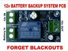
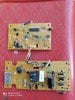
Basically I want to make a simple switch which can automatically transfer from 12v DC adapter supply to 12v battery backup in case of outage of supply from adapter. Please share some very simple circuit diagram. I want to use components from the circuit in attached picture. However switch should not restart the router.
 

Attachments

  • WhatsApp Image 2020-07-05 at 6.55.47 AM.jpeg
    WhatsApp Image 2020-07-05 at 6.55.47 AM.jpeg
    170.7 KB · Views: 13

davenn

Moderator
Sep 5, 2009
14,260
Joined
Sep 5, 2009
Messages
14,260
Hi and welcome :)

However switch should not restart the router.


Then you should consider doing what is done in normal UPS systems to avoid switching resets by running the item off the
battery and using a PSU to recharge the battery

Pretty much any other form of switching will drop the 12V to your units and cause a reset
 

(*steve*)

¡sǝpodᴉʇuɐ ǝɥʇ ɹɐǝɥd
Moderator
Jan 21, 2010
25,510
Joined
Jan 21, 2010
Messages
25,510
You can use a pair of diodes to isolate both supplies from each other. That way, if the mains 12V fails, the battery will take over.

However, this requires that the battery has a slightly lower voltage than the mains adapter. A far better approach is to have the 12V battery permanently attached to a charger, and power the device from the battery. In this case, the charger has to be one that *can* be left permanently connected, *and* will turn back on after a power failure.

The second option is the one suggested by Dave above.
 

Nauman Muhammad

May 9, 2016
77
Joined
May 9, 2016
Messages
77
You can use a pair of diodes to isolate both supplies from each other. That way, if the mains 12V fails, the battery will take over.

However, this requires that the battery has a slightly lower voltage than the mains adapter. A far better approach is to have the 12V battery permanently attached to a charger, and power the device from the battery. In this case, the charger has to be one that *can* be left permanently connected, *and* will turn back on after a power failure.

The second option is the one suggested by Dave above.


Thank you. But wouldn't it damage shorten the battery life due to continuous use, charging and discharging?
 
Last edited by a moderator:

(*steve*)

¡sǝpodᴉʇuɐ ǝɥʇ ɹɐǝɥd
Moderator
Jan 21, 2010
25,510
Joined
Jan 21, 2010
Messages
25,510
That may well work as long as the battery is the correct type and capacity for the charge controller. If you plan to connect your current 12V DC supply to the charge controller, be aware that solar charge controllers work on the basis that the power source is current limited. They can easily try to draw more current than a power supply can provide.
 

Nauman Muhammad

May 9, 2016
77
Joined
May 9, 2016
Messages
77
That may well work as long as the battery is the correct type and capacity for the charge controller. If you plan to connect your current 12V DC supply to the charge controller, be aware that solar charge controllers work on the basis that the power source is current limited. They can easily try to draw more current than a power supply can provide.
My router takes 2Amp, Planning to use battery of 4AH, and power supply of 5amp. Pwm controller is of 10A. What do you say?
 

(*steve*)

¡sǝpodᴉʇuɐ ǝɥʇ ɹɐǝɥd
Moderator
Jan 21, 2010
25,510
Joined
Jan 21, 2010
Messages
25,510
1) the 10A controller could try to draw 10A (or even more) from your 5A power supply. That's not good.
2) a 4AH battery is very low in capacity, are you sure the PWM controller will work with such a small battery? It may try to charge it too fast.
3) A 1.5 ohm 10W resistor in series with the 12V power supply should limit the current drawn by the PWM controller, whilst providing sufficient power to operate the router and charge the battery.

Give it a go and measure the current from the power supply after the unit has been running on the battery for maybe 30 minutes. If it's less that 5A you should be fine.

WARNING that resistor will get hot -- if it has mounting lugs it will need to be attached to a heatsink to be capable of dissipating the full rated power.

I'd also place a 3A fuse in series with the battery to protect yourself if your router develops a short.
 

Nauman Muhammad

May 9, 2016
77
Joined
May 9, 2016
Messages
77
1) the 10A controller could try to draw 10A (or even more) from your 5A power supply. That's not good.
2) a 4AH battery is very low in capacity, are you sure the PWM controller will work with such a small battery? It may try to charge it too fast.
3) A 1.5 ohm 10W resistor in series with the 12V power supply should limit the current drawn by the PWM controller, whilst providing sufficient power to operate the router and charge the battery.

Give it a go and measure the current from the power supply after the unit has been running on the battery for maybe 30 minutes. If it's less that 5A you should be fine.

WARNING that resistor will get hot -- if it has mounting lugs it will need to be attached to a heatsink to be capable of dissipating the full rated power.

I'd also place a 3A fuse in series with the battery to protect yourself if your router develops a short.
Thank you, but it isn't hassle free as well.
 

Nauman Muhammad

May 9, 2016
77
Joined
May 9, 2016
Messages
77
Can I make this type of thing with components available with me? Considering I have very basic electronic knowledge, I don't know all the components used in it.
 

Attachments

  • 1234__76278.1568166111.jpg
    1234__76278.1568166111.jpg
    176.6 KB · Views: 6

davenn

Moderator
Sep 5, 2009
14,260
Joined
Sep 5, 2009
Messages
14,260
Can I make this type of thing with components available with me? Considering I have very basic electronic knowledge, I don't know all the components used in it.


Without knowing the circuit, it's impossible to comment
It may be just a fancy switch and therefore giving a break in power to your gear
which is what you didnt want

a link to that module would be helpful ( ALWAYS post links :) )
 
Top