Maker Pro
Maker Pro

555 simple oscillator not working with small capacitors

snake0

Mar 30, 2014
54
Joined
Mar 30, 2014
Messages
54
Hi there, I'm trying to set up a simple oscillator that outputs 48kHz, however despite many different attempts all have fallen flat.

At present I am trying a 555 approach which is relatively simple, calculations as follows:

1440/48000 = 0.03 = (R1 + 2R2)xC1 [r1, r2 in kohm, c1 in uF]
(r1+ 2*r2) x 0.1u = 0.03

r1 + 2*r2 = 0.3k = 300 ohm
220 + 2*50 = 330 ... so a rough approximation, but should approach 48kHz.

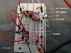
In order to see the output I am using a ghetto oscilloscope, basically an audio line hooked up in the circuit where you would normally put an oscilloscope, and the other end into my mic jack. It works surprisingly well.

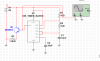
The problem I am having is that as I scale down the capacitors I lose 'sight' of any frequency. I have tried the above implementation, and a different implementation as seen in the circuit diagram attached that used 1k for both R1 and R2 and 10nF as my C1, but when I couldn't see the results as I scaled down to 10nF I instead opted for the above one which uses a larger 0.1uF capacitor.

As the results seem rather consistent before I hit 0.xx u, I know I am on the right track, but not sure how to resolve this situation. Any ideas?

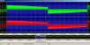
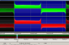
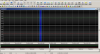
The result for C1=470uF in the sound program has been attached, as well as that for 47u, and 0.1uF. 0.1uF might just even be 'noise', and not the pulses, as its a sine wave not square.

Below are the results I obtain from experimenting with different caps:
C1 Period Freq
470u 0.167 5hz
47u 0.016 62hz
10u 0.004 250hz
1u 0.00035 2857hz
0.1u 0.0002 5000hz <- off by a factor of ten
 

Attachments

  • 555freqcircuit.png
    555freqcircuit.png
    14.2 KB · Views: 173
  • 555freq.jpg
    555freq.jpg
    151.6 KB · Views: 190
  • 470u.png
    470u.png
    34.7 KB · Views: 141
  • 47u.png
    47u.png
    29.2 KB · Views: 198
  • 0.1u.png
    0.1u.png
    46.9 KB · Views: 199

KrisBlueNZ

Sadly passed away in 2015
Nov 28, 2011
8,393
Joined
Nov 28, 2011
Messages
8,393
I'm not too sure what you're doing, but...

(1) You shouldn't use 300 ohm resistors with a 555. Use 1k at least, as shown on your schematic.

(2) A sound card will not record frequencies greater than around 20 kHz. Normally, sound cards sample at 44,100 samples per second, so according to Nyquist, 22.05 kHz is the highest frequency they can record, but the card has fairly steep filtering in the analogue domain to minimise aliasing, and this will remove frequencies above around 20 kHz, perhaps even lower.
 

jpanhalt

Nov 12, 2013
426
Joined
Nov 12, 2013
Messages
426
I have attached AN170 from Philips. It is no longer available on its site (last time I looked). It is worth the read.

upload_2014-4-11_10-13-52.png

John

Edit: Sorry, the file name is different. I can't change it. Maybe a moderator can.
 

Attachments

  • 555AN.pdf
    378.7 KB · Views: 84

snake0

Mar 30, 2014
54
Joined
Mar 30, 2014
Messages
54
I'm not too sure what you're doing, but...

(1) You shouldn't use 300 ohm resistors with a 555. Use 1k at least, as shown on your schematic.

(2) A sound card will not record frequencies greater than around 20 kHz. Normally, sound cards sample at 44,100 samples per second, so according to Nyquist, 22.05 kHz is the highest frequency they can record, but the card has fairly steep filtering in the analogue domain to minimise aliasing, and this will remove frequencies above around 20 kHz, perhaps even lower.

Thank you for confirming my suspicions!
I think I will just have to shell out for an oscilloscope, however I have heard bad things about the USB ones sold on Ebay and have been holding back so far. I don't have the funds for an expensive model though...

What I'm trying to do essentially is build a 48kHz oscillator to flash an IED for a detection circuit, however it is very difficult to do blind without seeing what frequency I am emitting at. The Infrared detector I have responds to 48kHz.
 

BobK

Jan 5, 2010
7,682
Joined
Jan 5, 2010
Messages
7,682
There are very cheap multimeters that can measure frequencies. One of those would be fine for your project.

Bob
 

KrisBlueNZ

Sadly passed away in 2015
Nov 28, 2011
8,393
Joined
Nov 28, 2011
Messages
8,393
A 555 is not an accurate frequency source. Your best option would be a crystal oscillator and a frequency divider.

If you need exactly 48.000 kHz, you can derive this frequency from many standard crystal frequencies, but the easiest option is a 6.144 MHz crystal frequency, divided by 128. This can be done using a CD4060 (http://www.digikey.com/product-detail/en/CD4060BE/296-2060-5-ND/67311) a 16-pin IC that includes the oscillator circuit to make the crystal oscillate, and a chain of cascaded divide-by-2 stages called a "ripple carry binary counter". A suitable crystal is: http://www.digikey.com/product-detail/en/HC49US-6.144MABJB/300-6013-ND/284201

Read the CD4060 data sheet to find out how to use the crystal with it, and how to determine which output will have 48.000 kHz on it.
 

BobK

Jan 5, 2010
7,682
Joined
Jan 5, 2010
Messages
7,682
Yep, they must be using a 555 in the Flight Data recorder for MA370. Expected frequency 37.5KHz, detected 33KHz.

Bob
 

snake0

Mar 30, 2014
54
Joined
Mar 30, 2014
Messages
54
Thanks for the suggestion Kris, I will look into obtaining that IC.

As a matter of fact I was using a ripple binary counter (JK flipflop) to divide the frequency so I could look at it via my sound card, but alas as soon as I get down to the nanofarad range it dissipates. May also be something to do with the caps I'm using, as I get consistent results with the aluminium cylinders, but problems with the polyester rectangles.
 

snake0

Mar 30, 2014
54
Joined
Mar 30, 2014
Messages
54
Hi Bob,

I might look into getting one of those multimeters, I just saw one in a book I was reading too! Thanks
 

neon

Oct 21, 2006
1,325
Joined
Oct 21, 2006
Messages
1,325
the comparator is laser trimmed by the vendor to .639 ratio and the ratio of duty cycle must be within 5% to 95% then it will oscillate to any frequency within set parameters. set any frequency you want but exceed the 5-95% set duty cycle and it quits
 

(*steve*)

¡sǝpodᴉʇuɐ ǝɥʇ ɹɐǝɥd
Moderator
Jan 21, 2010
25,510
Joined
Jan 21, 2010
Messages
25,510
the comparator is laser trimmed by the vendor to .639 ratio and the ratio of duty cycle must be within 5% to 95% then it will oscillate to any frequency within set parameters. set any frequency you want but exceed the 5-95% set duty cycle and it quits

That's almost 100% wrong.

555s are not laser trimmed, and duty cycles outside that range are commonly used.

The only laser trimmed 555 I could find was this one, and it's not a 555 timer...
 
Top