Maker Pro
Maker Pro

a simple noise filter, L or C

DuctDuck

Jan 26, 2013
52
Joined
Jan 26, 2013
Messages
52
How could I proceed in selecting a filtering circuit for a DC circuit being measured?

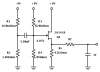
I have a 5pF capacitor being sensed by a jfet (i.e.-2n5459 gen.purp.); meaning the high impedance gate-source is parallel to the capacitor and its Rdischarge. Right now, 1.5kohm is jfet's Rs and is the input load/Rgen to a DC differential amplifier, meant to amplify the tiny DC fluctuations on the capacitor.

I don't want to have a parallel capacitor filter the DC fluctations nor do I want a series inductor too either. Possibly 60Hz, or better yet 6Hz, should be eliminated from the DC measurement signal.

Is there something I'm missing? A compromising point to reconcile with? Please fill me in!
 

CDRIVE

Hauling 10' pipe on a Trek Shift3
May 8, 2012
4,960
Joined
May 8, 2012
Messages
4,960
A schematic is always helpful.

Chris
 

DuctDuck

Jan 26, 2013
52
Joined
Jan 26, 2013
Messages
52
Yes, I quit agree...check out the thumbnail, please. You will see I have went with an RC integrator as the output for a CD jfet amplifier. Keep in mind this is a low DC voltage measuring circuit and not AC. I predict the RC time constant will have to be much smaller than the previous RC time constant.

p.s.-I would like to deal with the filter issue immediately before anything else.

p.s.s-I'm getting re-aquainted to using jfets again, so please be patient:)
 

Attachments

  • jfet-buffer-filter.png
    jfet-buffer-filter.png
    10.4 KB · Views: 156

duke37

Jan 9, 2011
5,364
Joined
Jan 9, 2011
Messages
5,364
I do not see where the DC signal comes in.

What frequency do you want to eliminate?
 

DuctDuck

Jan 26, 2013
52
Joined
Jan 26, 2013
Messages
52
Oh, sorry. The 5pF cap is an air capacitor I built as an ion chamber (i.e.-volume of air and its ions go to the plates), that is where the DC signal comes in.

The frequencies I want to be rid of are from infernal thermal noise. The S/N calculations point to an extremely low figure; perhaps a low corner frequency Lpf can change it around (e.g.- 60Hz).
 

duke37

Jan 9, 2011
5,364
Joined
Jan 9, 2011
Messages
5,364
I do not see how the ions will go to the plates without a potential to attract them.

To get a turn over frequency of about 10Hz, you need an R*C time constant of 0.1sec.
Use C=100nF, R=1M.

I believe that fets have high low frequency flicker noise.
 

CDRIVE

Hauling 10' pipe on a Trek Shift3
May 8, 2012
4,960
Joined
May 8, 2012
Messages
4,960
Biasing a JFET like a BJT is rather odd. It's putting it nearly outside its linear region.

Chris
 

DuctDuck

Jan 26, 2013
52
Joined
Jan 26, 2013
Messages
52
Yes, Duke37, yes the potential is there! The design of the capacitor uses a coaxial capacitance calculation, and when 5V is there at either plate with respect to ground or better source, there is enough electrostatics for attracting a minute Coulomb population (i.e.- 23.3625x10⁻¹² A worth as maximum).

I'm sorry, but I don't want to put any more capacitance on the input stage; after the buffer amp, Cf can then be very small returning minimal energy. No?
 

duke37

Jan 9, 2011
5,364
Joined
Jan 9, 2011
Messages
5,364
Sorry, I just assumed that the voltage supply at the top of the diagram was positive.

Once you have gone through the fet buffer, you have a low impedance source and a load of 1M will not affect it.
 

DuctDuck

Jan 26, 2013
52
Joined
Jan 26, 2013
Messages
52
Great, I will go with your low turnover frequency point of 10Hz, et al. Thanks Duke!

I have noticed some bjt/jfet/mosfet amplifiers using power supply decoupling techniques. Does a CD jfet require this too?
 

duke37

Jan 9, 2011
5,364
Joined
Jan 9, 2011
Messages
5,364
Your + and - supplies need to be very well smoothed as any variation will be fed directly to the 5pF capacitor. A large capacitor on the negative divider would help.
 

DuctDuck

Jan 26, 2013
52
Joined
Jan 26, 2013
Messages
52
I want to thank the positive efforts of all towards reducing my thermal noise question thread (e.g.- Vnoise=50uVrms, BW=<4kHz).

I have done some simulations and experiments using your contributions, and some more improvements to analysis and redesigning. This may have castoff your valuable input; sorry Duke, but it was valuable at the beginning of this.

Because I'm using a bjt differential amplifier I have had to reduce the filter's impedance; at the jfet's source branch. This brought me around to using two approaches to solving my problem; AC signal response and DC transient analysis (sorry I don't know plural for analysis...a-nal-i-se-s but how do you spell it???).

Rs=4.7kOhm
Rf=3.3kOhm
(Rt=<8.2kOhm)

Cf=10uF
fc=4.8Hz (and Av=0.01 at f>48Hz...nice)

Ultimately, the results proved very different from all of your valuable input. Not that you're plain wrong, its the contributions I valued and learned from. So, thanks again and keep on contributing!
 
Top