Maker Pro
Maker Pro

AC current sensing circuit/relay

bigharps

Oct 8, 2017
3
Joined
Oct 8, 2017
Messages
3
I'm new here, but hoping I may get some help.
I am a retired refrigeration and air conditioning technician and I have a project where I need to keep the motor current of a sealed unit compressor between about 5.5 and 6 amps for efficiency while the system is running.
There is a cooling pump I want to switch 'on' when the sealed unit current approaches 6A, and turn it off again when the current falls to about 5.5A. I'll actually be happy with any set-points between 5A and 6A.
My poor old brain keeps telling me there must be a simple way to do this, but I can find nothing commercially available to do the job. There are countless over-current devices which will switch at a set point, but these all seem to be manual reset.
Operating voltage and/or output capacity of any device are somewhat irrelevant, as I can use a transformer to get the required voltage and an output relay to get the needed switching capacity.
Any assistance would be appreciated. Thanks.
 

hevans1944

Hop - AC8NS
Jun 21, 2012
4,880
Joined
Jun 21, 2012
Messages
4,880
A Hall Effect current sensor driving an analog input of a PIC microprocessor makes a nice solution. Some assembly required, both hardware and software. Interested? Send a private message to @chopnhack, who has a thread here on how he did this to control a dust collector when AC current in woodworking tool motors exceeded his trip points. I know of no commercial off-the-shelf units that will do what you describe, but perhaps somebody here like @Minder (our resident motor expert) does.
 

Bluejets

Oct 5, 2014
6,922
Joined
Oct 5, 2014
Messages
6,922
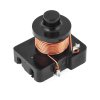
The older Tecumseh and probably many other sealed unit domestic compressors used to use a relay that had it's coil in series with the run winding and a set of contacts connected to the solenoid.

As you are probably aware, the purpose was to engage the start winding as the run was pulling higher current and then it would drop as the run tapered off.

Fairly simple arrangement with an accessible winding that you might be able to fiddle to get the right pull-in.

Just a thought as I would imagine the current would be somewhere around that figure.
 

Attachments

  • relay.jpg
    relay.jpg
    69.6 KB · Views: 119
Last edited:

Minder

Apr 24, 2015
3,478
Joined
Apr 24, 2015
Messages
3,478
You may have a problem finding a simple or off-the-shelf solution because of the precise set point and also the variation in current of a AC motor due to momentary current peaks etc.
There are current sense devices by Honeywell CSDA series etc, also the cheap ACS712 on ebay, but these have to be integrated with other devices, and to overcome the hysteresis problem a micro processor solution could be used.
If you use one of the current relays mentioned by Bluejets, you would need to find one that is the current operating point you need. Which may not be an easy task.
M.
 

bigharps

Oct 8, 2017
3
Joined
Oct 8, 2017
Messages
3
Ashampoo_Snap_2017.10.10_11h25m06s_002_.jpg Ashampoo_Snap_2017.10.10_13h35m08s_004_.jpg
I have done a bit more searching on the net and found this Omron module. It’s available in Australia, delivered, for less than $5.


Single Channel 5V OMRON SSR G3MB-202P Solid State Relay Module
  • 1 Channel High Level
  • 5V Omron solid state relay 240V 2A, output with resistive fuse 240V 2A
  • Size: 24*32*21mm/0.94*1.25*0.82”
  • Input Power: 5V DC (160mA)
  • Input control signal voltage:
    (0-2.5V state low relay OFF)
    (3-5V state high relay ON)
  • Module interface:
  • Input section:
  • DC +: positive power supply (by relay voltage power supply)
  • DC-: connect power negative
  • CH: relay module signal to trigger the end (high level trigger effective
  • Voltage version static current working current trigger voltage trigger current
    5V 0mA 12.5mA 3.3-5V 2mA

I am thinking of coupling it with a CT sensor. I have six of the sensors (data above) from an energy monitor I scrapped a few years ago (NEVER, EVER toss anything out!)


I intend to use a 5Vdc power supply for the supply voltage, and use the CT output current across a resistor for the trigger voltage. I’ll put a bridge rectifier in the CT output to get my dc for the trigger and I think I’ll loop the current carrying cable through the sensor 4 times to up its output and reduce the resistor size.

If I size the resistor to give me 3V @ 6A motor current, the output voltage should drop to 2.5V at 5A, which will fit well enough with my needs. Will take some fiddling, but I think it should work.
Can you think of a reason this would not work for my application discussed above?
 

Minder

Apr 24, 2015
3,478
Joined
Apr 24, 2015
Messages
3,478
With experimentation you may get it to work, A CT requires a burden resistor in order to prevent excess voltage.
M.
 

bigharps

Oct 8, 2017
3
Joined
Oct 8, 2017
Messages
3
With experimentation you may get it to work, A CT requires a burden resistor in order to prevent excess voltage.
M.
I did mention "and use the CT output current across a resistor for the trigger voltage." in my post.
Might take a lot of fiddling, but I think it will work.
 
Top