Maker Pro
Maker Pro

Adding a pot to a hot air gun to control airflow

eKretz

Apr 8, 2013
251
Joined
Apr 8, 2013
Messages
251
edit: moved from https://www.electronicspoint.com/frankensteins-components-t254697p2.html

It's adjustable from 70°F to 1100°F. Yeah the airflow has 2 range settings, the low one works great, the high one is a little overblown, forgive the pun, heh.

That nozzle was just a 10 minute quickie, but it works pretty well.

Edit: I actually just had it apart tonight, the LCD temp display was missing half of it's digits, so I yanked it apart and found a few wires that had popped off the solder joints on the board. Problem's gone now! But anyways, I was thinking about adding a pot to the blower motor instead of just the 2 position switch to get infinite adjustability. Do you think it would be worth doing?

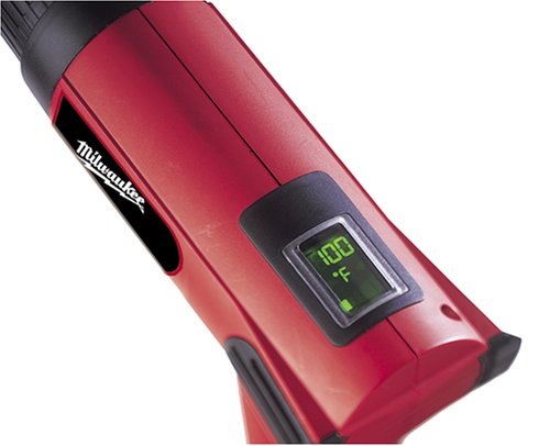
Here's a shot of the LCD panel, you can control temp to within 10 degrees. You move the slider on the handle and the display switches momentarily to "setting" mode, then after a few seconds of no movement it goes back into "reading" mode. It's got a closed circuit loop so it can adjust temperature on the fly to compensate for the different airflow settings.

milheat.jpg:original
 
Last edited by a moderator:

quantumtangles

Dec 19, 2012
153
Joined
Dec 19, 2012
Messages
153
Hot Air Gun

Great idea to add a potentiometer. It would be fully adjustable but as well as that, you have a heat gun handle instead of the soldering iron type handles that soldering station hot air guns invariably come with.

Great project and very useful. You could also use it to affix surface mount components using solder paste :D
 

eKretz

Apr 8, 2013
251
Joined
Apr 8, 2013
Messages
251
Thanks! I've been digging through my scrap parts pile looking for a decent pot, but no luck yet. It is quite nice having the big heat gun actually, I can run it for hours and the handle stays room temp, but I usually hold it by the barrel right behind the black collar. It warms up a little bit more here, but it never gets uncomfortable. I bet it would work great for SMD work with paste if I got some stencils.
 

(*steve*)

¡sǝpodᴉʇuɐ ǝɥʇ ɹɐǝɥd
Moderator
Jan 21, 2010
25,510
Joined
Jan 21, 2010
Messages
25,510
It is very unlikely that you can use a pot to control the speed of the blower.

The switch almost certainly changes between pair of windings, each giving a different speed.
 

quantumtangles

Dec 19, 2012
153
Joined
Dec 19, 2012
Messages
153
It is very unlikely that you can use a pot to control the speed of the blower.

The switch almost certainly changes between pair of windings, each giving a different speed.

I think Steve may be right about this.

Having said that, could a Pot operate to change resistance and therefore voltage levels for the winding it is connected to? If that is not so, read no further. But if that is so, could two pots be added (one to each set of windings) or would this be to misunderstand or be a bridge too far?

Is it misconceived because you say the two sets of windings form an electromagnet coupling of some sort (as in the primary and secondary coils in a transformer?) or misconceived because variable potentiometers cannot allow changes of resistance in each set of windings and accordingly cannot permit voltage level control in each winding?

Incidentally, I had in mind connecting the Pot or Pots directly to the relevant windings rather than to the terminals of the switch.

Apologies in advance if I have fundamentally misunderstood the problem.
 
Last edited:

(*steve*)

¡sǝpodᴉʇuɐ ǝɥʇ ɹɐǝɥd
Moderator
Jan 21, 2010
25,510
Joined
Jan 21, 2010
Messages
25,510
The major issue is that a resistor is not a great way to change the speed of a motor.

The next issue is that if you try, you'll need a VERY high power pot

Most variable speed motors (like those used in fans)

There is some explanation here.
 

eKretz

Apr 8, 2013
251
Joined
Apr 8, 2013
Messages
251
Interesting article. I am pretty sure it's an AC motor since it plugs into the wall, but I need to double-check that. Would I be able to add a small circuit with a spare MOSFET to control it if it's DC or would I need a whole driver chip, et al?

P.S. Steve, did you see my question in the h-bridge post? or get my PM?
 
Last edited:

(*steve*)

¡sǝpodᴉʇuɐ ǝɥʇ ɹɐǝɥd
Moderator
Jan 21, 2010
25,510
Joined
Jan 21, 2010
Messages
25,510
Interesting article. I am pretty sure it's an AC motor since it plugs into the wall, but I need to double-check that. Would I be able to add a small circuit with a spare MOSFET to control it if it's DC or would I need a whole driver chip, et al?

Not sure what you could use.

P.S. Steve, did you see my question in the h-bridge post? or get my PM?

No to both.
 

(*steve*)

¡sǝpodᴉʇuɐ ǝɥʇ ɹɐǝɥd
Moderator
Jan 21, 2010
25,510
Joined
Jan 21, 2010
Messages
25,510
The problem with using a pot is the power dissipated in it.

Let's say you decided on a 5k pot, and that the maximum current through the motor is 50mA

The power rating required for the pot is I^2 R = 12.5W. Look at the price (and size) of such a pot.

If your motor actually requires 100mA, the pot needs to be 50W.

There is a reason the very next slide in your link says that switching inductors have the advantage of lower power dissipation.
 

CocaCola

Apr 7, 2012
3,635
Joined
Apr 7, 2012
Messages
3,635
Save yourself a lot of hassle and just get a 'embossing heat gun' I use the heck out of mine when I don't want to fire up the real rework station..

I can get these all day at most craft stores (Jo-Anne, Hobby Lobby) by me that have 40% or 50% off one item coupons almost every week...

Like this week it's 40% off already, not a great deal but just the same...
http://www.joann.com/american-crafts-zap-embossing-heat-gun/zprd_10066181a/

Or
http://shop.hobbylobby.com/products/pink-heat-embossing-gun-506345/

And with Hobby Lobbys current 40% off coupon you are out the door for $12...

These guns get plenty hot to rework boards and the air stream is not crazy strong like traditional paint stripping hot air guns...
 

eKretz

Apr 8, 2013
251
Joined
Apr 8, 2013
Messages
251
Well, it works fine on the low fan setting, it actually is pretty weak on low. I just thought it would be nice to be able to adjust the blower speed; then I could use very very low or kick it up to high and adjust it down. It turns out it's a DC motor anyways, low runs @12V and hi runs @24V. Thanks for the link and info though!
 

eKretz

Apr 8, 2013
251
Joined
Apr 8, 2013
Messages
251
Quote:
P.S. Steve, did you see my question in the h-bridge post? or get my PM?
No to both.

So, umm, did I do something to tick you off? Or...?
 

eKretz

Apr 8, 2013
251
Joined
Apr 8, 2013
Messages
251
So we've established that it's probably not cost effective to do this project with a pot, but just for the educational aspect of it, what about a DC PWM switching regulator? Or would that be ridiculously expensive also?

Say something like this MX033: PWM DC Motor Speed Control Module:

http://store.qkits.com/category.cfm/DCMOTOR
 
Last edited:

(*steve*)

¡sǝpodᴉʇuɐ ǝɥʇ ɹɐǝɥd
Moderator
Jan 21, 2010
25,510
Joined
Jan 21, 2010
Messages
25,510
So, umm, did I do something to tick you off? Or...?

No, I just didn't get a PM, and I don't recall the thread you're talking about.

Send me another PM and remind me which thread it was and I'll take a look :)
 

(*steve*)

¡sǝpodᴉʇuɐ ǝɥʇ ɹɐǝɥd
Moderator
Jan 21, 2010
25,510
Joined
Jan 21, 2010
Messages
25,510
It turns out it's a DC motor anyways, low runs @12V and hi runs @24V.

what about a DC PWM switching regulator? Or would that be ridiculously expensive also?

Say something like this MX033: PWM DC Motor Speed Control Module:

http://store.qkits.com/category.cfm/DCMOTOR

If it is actually running from DC, then a switchmode regulator capable of setting the output voltage between 12 and 24 volts would work.

I'd be very cautious because if it really is running from DC, it may not be isolated from the mains.

PWM would also work In both cases you'd leave the switch in the "high" position and use some new control to vary the speed.

You would also need to be careful about the current so as not to overload your regulator or PWM controller.

And the big thing is finding somewhere to mount it that's safe and not too hot.
 

eKretz

Apr 8, 2013
251
Joined
Apr 8, 2013
Messages
251
OK, I'll try sending you another PM. Last time when I did so, on the PM screen it changed your name from (*steve*) to something that looked like Alienware font, that didn't spell anything as far as I could tell.

The funny thing about the voltage when I checked it is that it showed both AC and DC voltage. When I checked with the multimeter on AC it showed 3 & 3.2VAC, (lo and hi) but when I checked with DC it showed 12 & 24VDC. I don't have an o'scope yet (hopefully soon) so I'm not sure what the heck is going on. Is that normal? As far as the heat goes, the handle area of the gun stays room temperature and there's quite a bit of room there, so it could go there if I decided to try it.
 

eKretz

Apr 8, 2013
251
Joined
Apr 8, 2013
Messages
251
OK, new developments! Picked up my first oscilloscope and checked out the waveform to the motor. Here is what I discovered:

On motor low setting, I get a pulsed DC waveform that switches between 12 and 20VDC, with a frequency of 60Hz and a positive duty cycle of 30%. On high, it switches between 21 and 29VDC, with a frequency of 120Hz and positive duty cycle of 60%. So that's where it was picking up the AC signal.

So I guess it's either already running some type of switching circuit or I have heard of "chopping." Could it be doing that?
 

(*steve*)

¡sǝpodᴉʇuɐ ǝɥʇ ɹɐǝɥd
Moderator
Jan 21, 2010
25,510
Joined
Jan 21, 2010
Messages
25,510
Sounds like it's running from half or full wave rectified AC.

You weren't using a 10x probe were you?

edit: a picture of the scope display would be very useful.
 

eKretz

Apr 8, 2013
251
Joined
Apr 8, 2013
Messages
251
Ohh, you're right, I didn't think of that...the waveform shape is completely wrong for a switched supply. I just investigated inside the handle and there are several diodes under there. And yes, I was using a 10x probe, but it was compensated. This time I used a 1x probe to get these pics though:

Low setting:

image-4.jpg~original


High setting:

image-5.jpg~original


Was the only reason you asked about the probe to make sure the numbers were right? Or is there another reason that I should know about but don't since I'm a 'scope noob?

Now that I look a little closer, it seems that maybe the AC was just rectified on low, just passing through the tops of the AC waveforms, and on high, it is flipping the bottom waveforms of the AC up to the top. Sorry, I'm not really familiar with the proper terms yet. Would those be half and full-wave rectified?
 
Last edited:
Top