Maker Pro
Maker Pro

Adding LEDs to already existing LEDs on PCB?

SouthSeaPirate

Mar 12, 2017
4
Joined
Mar 12, 2017
Messages
4
Hi all, total noob here!
Im looking at a project and would like to know how involved, if at all possible, to extend LEDs on a manufactured PCM.
Specifically a home router that has the LEDs directly on the PCB. I would like to add LEDs on a wire set so the LED would be emitting light away from the PCB.
What is needed?

2017_03_11_165_2c00c85e8dbb8da9581f.jpg


2017_03_11_166_39d250a35be7094358c1.jpg
 

73's de Edd

Aug 21, 2015
3,622
Joined
Aug 21, 2015
Messages
3,622
.

Sir SouthSeaPirate. . . . . . . .aka . . . . . AAAAAAAAAAAARRRGH MATEY !

Since I am seeing only 7 internal LED's, that would just be a match for this one chip interfacing circuit, that is just stuffed with transistors.
It would totally snooze on the meager drive currents to each cloned 20ma Hi Intensity LED . . .mounted offboard . . . . .being wire connected .


Units Relevant Schematic:
MULTIPLE LED Driver Circuit.png

IC's datasheet :

http://pdf.datasheetcatalog.com/datasheet2/f/0c6x6a46ig46qlxf3j2qsaii8o3y.pdf


73s de Edd
 

SouthSeaPirate

Mar 12, 2017
4
Joined
Mar 12, 2017
Messages
4
Way above my head lol
So you think I could just wire in 20ma LEDs on each and be fine?
Can I multimeter the onboard LEDs and get the proper voltage read out?
Need to know what I gotta buy ahead of time cause I don't live anywhere near an electronics store.
Thanks so much for the help!
 

73's de Edd

Aug 21, 2015
3,622
Joined
Aug 21, 2015
Messages
3,622
Sir SouthSeaPirate. . . . . . . .

Not even scratching the surface of my head . . . . .

So you think I could just wire in 20ma LEDs on each and be fine?

NOPE . . . .LED's don't readily share . . . . unless you are OK with . . .vewy-vewy dim..
You need to use that isolative manner prescribed . . . the original LED's won't EVEN slightly detect the additional remoted LEDs presence and that added set will operate like gangbusters.

You need to give the supply voltage coming in from the wall wart connector at the top left corner.

I can see the 1 .8 V and 3.3 supply lines but wonder about the highest DC voltage level present.

Need a memory refresh . . . . I know about the typical / activity flashing functions, but what are the ratio of lit LEDS to unlit ones ?

73s de Edd
 

SouthSeaPirate

Mar 12, 2017
4
Joined
Mar 12, 2017
Messages
4
Four of the LEDs would be lit if the there is a signal on the network jacks. Those I dont care about.
The ones I do care about are the wireless on, DSL, and power on.

No I do not want dim.

I misunderstood your first post. I thought you were saying that was the chip inside the router, not what I need to make this work.
 

SouthSeaPirate

Mar 12, 2017
4
Joined
Mar 12, 2017
Messages
4
On the schematic, does 'TO LEDS' refer to patching to the LEDs on the board?
If so, what side of the on board LEDs to solder to? Assuming it maters.
'LED 1' and so forth refer to my remote LED's yes?
What resistors do I need? I see 1/2watt, 1/4watt, etc.

Sorry, I just dont know this stuff. Im a follow the manual kind of guy, not a figure it out kinda guy.
 

73's de Edd

Aug 21, 2015
3,622
Joined
Aug 21, 2015
Messages
3,622
Sir SouthSeaPirate . . . . . . . .

On the schematic, does 'TO LEDS' refer to patching to the LEDs on the board?

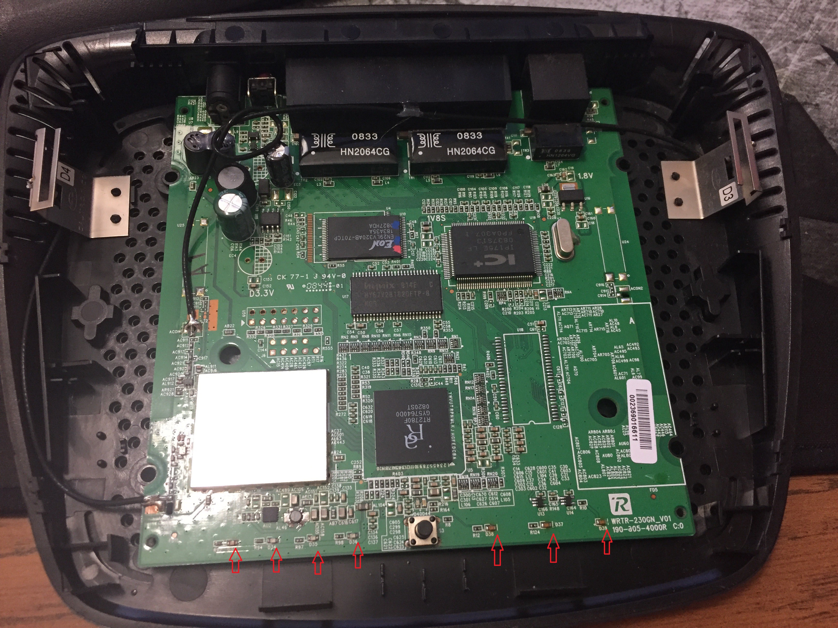
At each of the on board LEDs, they have their current limiting, surface mount resistor being just to their side.
At that junction is where you would want to solder tack in a small gauge wire
*** that goes BACK to an associated 47k base resistor.


If so, what side of the on board LEDs to solder to? Assuming it matters.

You are soldering to the top, component side of the board

'LED 1' and so forth refer to my remote LED's yes?

Yeth


What resistors do I need? I see 1/2watt, 1/4watt, etc.

The left set could use 1/4 watt, the right set would loaf with 1/2 watt units


My personal construction technique would be to use some fine gauge insulated "wire wrap" wire and connect one to each junction and thread bind them and route the amassed cable bunch back to the left side of the board where the IC would be mounted.
Each wire is then going to its associative 47K res at the IC.

*** If you have none, the best available source after that would be some of the 26 ga insulated copper wire stripped from a CAT 5 cable.

Also if you have ZERO pcb fabrication experience, since this is being a linear . . . in one side . . . out the other side, it might incorporate "dead bug" mount configuration of the IC.

In that situation, the IC is mounted legs up, on a small insulative board with a drop of super glue, and the leads splayed out, such that wire connections can then be made to them . . . . . such as is being seen at the two left leads in the foreground below.

ILLUSTRATION:

F3YFHQSI504WR73.MEDIUM.jpg


Then, you build up the mounting and wiring of the wire remoted LED's, as you wound have them.

STILL need the DC voltage level coming from the DC power wall wart connector, as seen at the units left rear.

73s de Edd


.
 
Last edited:
Top