Tb_NSX999MKII
- May 8, 2021
- 2
- Joined
- May 8, 2021
- Messages
- 2
Good afternoon!
I bought a non-functional AIWA NSX999MKII stereo system from ebay.
The consequence of the problem is that, as soon as I insert the power cord into the mains outlet, the two 5 A fuses at the end of the transformer burn.
Here is what I did so far:
-The problems immediately spotted:
-- The FET transistor Q212 was not properly connected to the circuit board:
it was mechanically attached to the board, but the solder had cracked/ there was not a proper electrical contact. I could and did take it out of the board with two fingers.
Resistance measurement revealed no short circuit.
I re-soldered it properly to the board.
However, I just read user @ArFa Daily response to thread:
https://www.electronicspoint.com/forums/threads/aiwa-nsx-999-service-manual.68042/
He says
"
These FETs fail and cause all sorts of problems. You only have
to look at them wrongly for them to fail all on their own
"
So, maybe, their inadequate coupling to the board caused some problems downstream.
-- A resistor connecting two metallic component covers was shorted because it was touching one of them.
-- An anchoring leg connecting the speaker outputs to the PCB had the same problem as O212: solder cracked and the component was free to move.
Fixing these mechanical faults did not solve the short.
Then I tied the following:
- The transformer works fine as far as I understand from measuring it:
Measuring the AC voltage output with reference to the central pin, pin 3, I found:
V31 = V35 = 52 V~
V32 = V34 = 21.4 V~.
This measurement was done with the transformer output disconnected from the main PCB, as any attempt to connect it would blow the fuses.
- Then, with the help of the electronist from the university, who kindly allowed me to use the Weller vacuum assisted components removal tool, we disconnected the STK 4231II IC.
Without the IC power amp on board, the fuses stay intact.
- The first rectifying bridge, D101, received 42 V AC (between middle 2-3 pins) and outputs 55.5/6 VDC between the external 1-4 pins labeled +, respectively -.
- The second bridge, D116, is activated by a relay, which I think is controlled by another event triggered from elsewhere / another board. The result is a 0V AC between the input terminals, which are not connected to the transformer as the relay is normally open.
- The STK 4231II:
-- In free space/ out from the board, I measured the resistance between all the combinations of pins 1-22 and found no shorts.
R13-15 = 90 Ohms was the smallest I found.
-- On the actual board, the situation was different:
There are three grounded pins:
5, 8, 18.
Also, there are the following shorted pins:
9-10, 10-11, 11-16, 13-15;
9-11,
9-16, 10-16.
Looking at the schematic, and tracing the currents, but with the eye of an amateur and without a solid understanding, most of the shorts made sense.
What I don't understand is the following.
Pin 16 should be at a potential of -20.7 V and pin 9 should be at a potential of + 20.7 V, if I understand correctly.
In reality, they are shorted on the board.
From what I have done so far, my conclusion is that the short is coming from somewhere on the PCB, after the STK IC. This may, very well, be incorrect.
If you are familiar with the Aiwa stereo, what is your opinion, please?
What elements would be affected by a loosely connected Q212 ?
How could I alert/ tag user @ Arfa Daily in a message?
His name no longer appears in the list.
This stereo was made in UK, so I hope/ am expecting to be able to find some electronic engineers that have worked at the Aiwa factory.
Thank you.
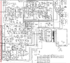
Attached is the schematic for the transformer and amp. I could not attach the entire schematic diagram as it was too large.
I bought a non-functional AIWA NSX999MKII stereo system from ebay.
The consequence of the problem is that, as soon as I insert the power cord into the mains outlet, the two 5 A fuses at the end of the transformer burn.
Here is what I did so far:
-The problems immediately spotted:
-- The FET transistor Q212 was not properly connected to the circuit board:
it was mechanically attached to the board, but the solder had cracked/ there was not a proper electrical contact. I could and did take it out of the board with two fingers.
Resistance measurement revealed no short circuit.
I re-soldered it properly to the board.
However, I just read user @ArFa Daily response to thread:
https://www.electronicspoint.com/forums/threads/aiwa-nsx-999-service-manual.68042/
He says
"
These FETs fail and cause all sorts of problems. You only have
to look at them wrongly for them to fail all on their own
"
So, maybe, their inadequate coupling to the board caused some problems downstream.
-- A resistor connecting two metallic component covers was shorted because it was touching one of them.
-- An anchoring leg connecting the speaker outputs to the PCB had the same problem as O212: solder cracked and the component was free to move.
Fixing these mechanical faults did not solve the short.
Then I tied the following:
- The transformer works fine as far as I understand from measuring it:
Measuring the AC voltage output with reference to the central pin, pin 3, I found:
V31 = V35 = 52 V~
V32 = V34 = 21.4 V~.
This measurement was done with the transformer output disconnected from the main PCB, as any attempt to connect it would blow the fuses.
- Then, with the help of the electronist from the university, who kindly allowed me to use the Weller vacuum assisted components removal tool, we disconnected the STK 4231II IC.
Without the IC power amp on board, the fuses stay intact.
- The first rectifying bridge, D101, received 42 V AC (between middle 2-3 pins) and outputs 55.5/6 VDC between the external 1-4 pins labeled +, respectively -.
- The second bridge, D116, is activated by a relay, which I think is controlled by another event triggered from elsewhere / another board. The result is a 0V AC between the input terminals, which are not connected to the transformer as the relay is normally open.
- The STK 4231II:
-- In free space/ out from the board, I measured the resistance between all the combinations of pins 1-22 and found no shorts.
R13-15 = 90 Ohms was the smallest I found.
-- On the actual board, the situation was different:
There are three grounded pins:
5, 8, 18.
Also, there are the following shorted pins:
9-10, 10-11, 11-16, 13-15;
9-11,
9-16, 10-16.
Looking at the schematic, and tracing the currents, but with the eye of an amateur and without a solid understanding, most of the shorts made sense.
What I don't understand is the following.
Pin 16 should be at a potential of -20.7 V and pin 9 should be at a potential of + 20.7 V, if I understand correctly.
In reality, they are shorted on the board.
From what I have done so far, my conclusion is that the short is coming from somewhere on the PCB, after the STK IC. This may, very well, be incorrect.
If you are familiar with the Aiwa stereo, what is your opinion, please?
What elements would be affected by a loosely connected Q212 ?
How could I alert/ tag user @ Arfa Daily in a message?
His name no longer appears in the list.
This stereo was made in UK, so I hope/ am expecting to be able to find some electronic engineers that have worked at the Aiwa factory.
Thank you.
Attached is the schematic for the transformer and amp. I could not attach the entire schematic diagram as it was too large.
Attachments
Last edited: