Maker Pro
Maker Pro

Amplifier SMPS died mid play

CrashDown963

Apr 9, 2023
7
Joined
Apr 9, 2023
Messages
7
Hello everyone!
I've got my Linn Av 5125 which, mid play (volume was pretty high), died altogether.
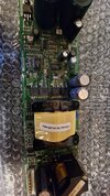
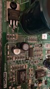
Opened it up, and removed the SMPS from the unit, obvious burn mark on one of the resistors (R222, probably a current shunt, located in the bottom center of the board), tried powering it with a halogen attached, no voltage on output rails.
Fuse is not blown and tested good, changed it for good measure.
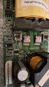
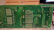
Mosfets not tested yet, due to annoying solder matrix on the underside which requires a heat gun (which i am, arguably, bad at using).
We're talking about a 500W unit, two rails, 36V.
I haven't tested any of the caps yet (I've tested them with capacitance mode, in circuit, so nothing reliable really), but I measured some opens on many diodes which I am going to outline. Would you guys have any suggestion on what happened, and what could be done to fix this?SMPS_1.jpg20230405_133412.jpg20230407_180003.jpg20230407_175955.jpg20230405_133451.jpg
 

kellys_eye

Jun 25, 2010
6,043
Joined
Jun 25, 2010
Messages
6,043
You're going to need an (isolated) oscilloscope for this I reckon..... not an 'un' complicated version of SMPS that's for sure so you'll have to go from basics.

Fortunately all the main control components are fully identified - the SG3524 (SMPS controller) and IR2110 (MOSFET driver) etc so finding the right signals is straightforward. Any luck finding a schematic?

I suggest you start by seeing if you can buy a replacement! Then identify the various sections of the SMPS - input, filter, rectifier, smoothing, switching, control etc. Remove all the main switching FETs then work to get the correct drive signals to them (via that driver chip) starting with the input circuit and DC rectification/smoothing.

Not sure if it's an artefact of the image(s) but I seem to be able to see some other blown device???? Might need some more close-ups of the board to identify them.
 

CrashDown963

Apr 9, 2023
7
Joined
Apr 9, 2023
Messages
7
You're going to need an (isolated) oscilloscope for this I reckon..... not an 'un' complicated version of SMPS that's for sure so you'll have to go from basics.

Fortunately all the main control components are fully identified - the SG3524 (SMPS controller) and IR2110 (MOSFET driver) etc so finding the right signals is straightforward. Any luck finding a schematic?

I suggest you start by seeing if you can buy a replacement! Then identify the various sections of the SMPS - input, filter, rectifier, smoothing, switching, control etc. Remove all the main switching FETs then work to get the correct drive signals to them (via that driver chip) starting with the input circuit and DC rectification/smoothing.

Not sure if it's an artefact of the image(s) but I seem to be able to see some other blown device???? Might need some more close-ups of the board to identify them.
Hello there!
I'm definitely not an expert. You could call me an amateur, when it comes down to power supplies, but I could tell this was definitely not a simple one...
Not a chance about the schematics, since the manifacturer straight up refuses to share them.
I did map out the output stage, since it's pretty simple, but that middle section... ugh
Unfortunately the board is very hard to find, so no luck on that department either...
I'll post some more pictures tomorrow, or straight up links to the parts links, for clarity
Was really hoping I didn't have to remove the fets, but I sure as he'll trust your judgment
Finally, what elements are you referring to? To a visual inspection, everything seems quite allright.
Thank you for your time, still!!
 

kellys_eye

Jun 25, 2010
6,043
Joined
Jun 25, 2010
Messages
6,043
You shouldn't have to remove the FETs entirely, just lift the (2) pins until you can assess their status. With clear enough pics we can also determine where to 'break' the power path to isolate the relevant sections and fault-find/repair in a logical manner.

There are tutorials on Youtube on SMPS repair that may prove useful to get an understanding of the processes involved - suggest you view a couple before tackling your own. We'll offer as much advice as we can.
 

CrashDown963

Apr 9, 2023
7
Joined
Apr 9, 2023
Messages
7
Hey guys!
I took your advices, and started watching some videos on SMPS. I still find it painful to trace everything by eye, without a schematic, but what can you do...
Regardless, first things fist, input stage is fine, up to the voltage regulator, which reads 300V on INPUT, and a whole short between ADJ and OUT. He has to go
I'll keep watching videos and work on this, any advice is good, especially if I say something very wrong
Thanks everyone again!!!
 

kellys_eye

Jun 25, 2010
6,043
Joined
Jun 25, 2010
Messages
6,043
Before removing the suspect regulator, snip the lead where the leg bends (the 'knee') of the 'adj' terminal and check again. External parts may cause what looks like a short and can be misleading. Have you measured any DC at the 'out' pin of that regulator???

I hope it isn't 300V!!!!
 

CrashDown963

Apr 9, 2023
7
Joined
Apr 9, 2023
Messages
7
Before removing the suspect regulator, snip the lead where the leg bends (the 'knee') of the 'adj' terminal and check again. External parts may cause what looks like a short and can be misleading. Have you measured any DC at the 'out' pin of that regulator???

I hope it isn't 300V!!!!
Oh nono, it's reading 0 on output, also checked a few components in parallel with it, and they have no voltage either.
Also why would i not just remove it alltogether at this point? It's not particularly inconvenient to remove, unlike the other fets on the next transformer...
Now I'm going to sleep, I'll check out any posts tomorrow.
I really really appreciate the help, thank you
 

Bluejets

Oct 5, 2014
6,586
Joined
Oct 5, 2014
Messages
6,586
Also why would i not just remove it alltogether at this point?
As I already mentioned, removal will be difficult without damaging the pcb traces.
These boards are invariably made with lead free solder and the traces suck all the heat out of the soldering iron if you try to remove the device.
You "might" manage to get one device leg up, but chances are the heat will destroy a possibly good device.

VB408 is a high voltage (400v) regulator.
 

Attachments

  • VB408.pdf
    166.6 KB · Views: 1
Last edited:

CrashDown963

Apr 9, 2023
7
Joined
Apr 9, 2023
Messages
7
As I already mentioned, removal will be difficult without damaging the pcb traces.
These boards are invariably made with lead free solder and the traces suck all the heat out of the soldering iron if you try to remove the device.
You "might" manage to get one device leg up, but chances are the heat will destroy a possibly good device.

VB408 is a high voltage (400v) regulator.
I guess, but i still have to do it, unfortunately.
Worst part is getting the VB408, pretty hard to find, high prices even on Ali, do you have any idea if i can replace it with something else?
 

kellys_eye

Jun 25, 2010
6,043
Joined
Jun 25, 2010
Messages
6,043
you have any idea if i can replace it with something else?
Not sure about an alternative but we should be able to determine what voltage it is meant to be outputting and you could then apply that voltage from an alternative source to see if the rest of the circuitry is working (or to affect repairs/see if it's worth doing etc).

To ensure your safety, all this really should be done through a mains isolating transformer......
 

CrashDown963

Apr 9, 2023
7
Joined
Apr 9, 2023
Messages
7
Not sure about an alternative but we should be able to determine what voltage it is meant to be outputting and you could then apply that voltage from an alternative source to see if the rest of the circuitry is working (or to affect repairs/see if it's worth doing etc).

To ensure your safety, all this really should be done through a mains isolating transformer......
What would the optimal way to determine such voltage be?
To be fair, I don't really want to get a 300V DC electrocution
 

Bluejets

Oct 5, 2014
6,586
Joined
Oct 5, 2014
Messages
6,586
but we should be able to determine what voltage it is meant to be outputting
Spec sheet says anything from 1.25v to input minus 30v......... shouldn't be too difficult to put a multimeter on it ad see what it actually is.
If in the above range, forget it as a problem.
You're looking for a fault that blows mosfet resistors......
 

kellys_eye

Jun 25, 2010
6,043
Joined
Jun 25, 2010
Messages
6,043
What would the optimal way to determine such voltage be?
That regulator uses external resistors to set the output voltage so you can trace which ones are connected to the 'adj' pin (and ground) and figure it out from the datasheet.
 

Sunnysky

Jul 15, 2016
540
Joined
Jul 15, 2016
Messages
540
This ought to be returned to supplied and request an RMA. It is beyond normal repair.

The damage is extensive and clues from the Cap outgassing and mylar discoloration without a blown fuse, indicate an unstable condition resulting in excessive thermal losses.

Assuming interconnections are proper, I can only guess that the DC source did not have a low enough ESR necessary to avoid spurious resonances under certain conditions perhaps with cross-conduction.

1681314023157.png
 

Bluejets

Oct 5, 2014
6,586
Joined
Oct 5, 2014
Messages
6,586
The damage is extensive and clues from the Cap outgassing and mylar discoloration without a blown fuse, indicate an unstable condition resulting in excessive thermal losses.

Assuming interconnections are proper, I can only guess that the DC source did not have a low enough ESR necessary to avoid spurious resonances under certain conditions perhaps with cross-conduction.
Yup, that certainly helped I don't think......
all that from a photo of a surface mount blown resistor..
 
Top