Maker Pro
Maker Pro

AMS1117-3.3 from 5VDC show 0.09vdc

StealthRT

Sep 4, 2010
146
Joined
Sep 4, 2010
Messages
146
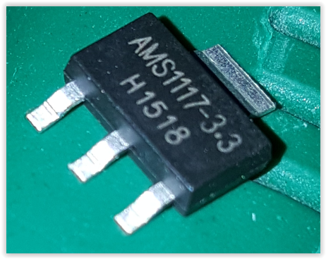
Hey all I am having an issue using this AMS1117-3.3 SMD:

tRUDe.png


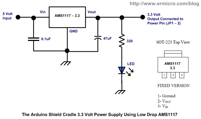
According to its documents it says its either a fixed or adjustable version? So I hook it up as I see in the documents:

Hc8fV.png


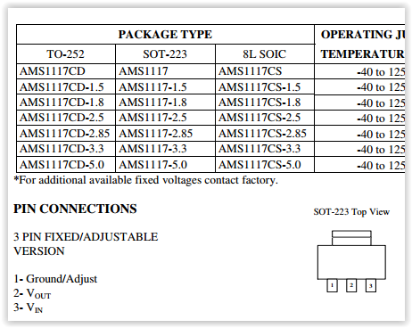
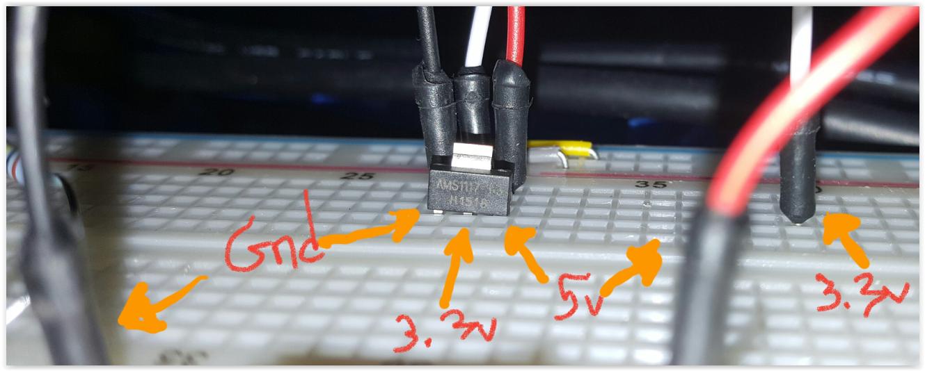
The left pin (1) being Ground.
The middle pin (2) being the 3.3vdc output.
The right pin (3) being the 5vdc input.

Once I hook all those up, I test it with my voltmeter on 20 and i get a reading of 0.09vdc????????

I've already tried 3 of these to make sure I didnt blow it or anything but it keeps saying that readout.

Am I missing something here? This must be the adjustable version since I can not just hook it up and expect 3.3vdc to come out?

I also tried to just step down from 5vdc to 3.3vdc using 100ohm resistor but that only produced around 4vdc output....

Here is the way I hooked it up:

rq8jf.jpg


The document I am reading is HERE


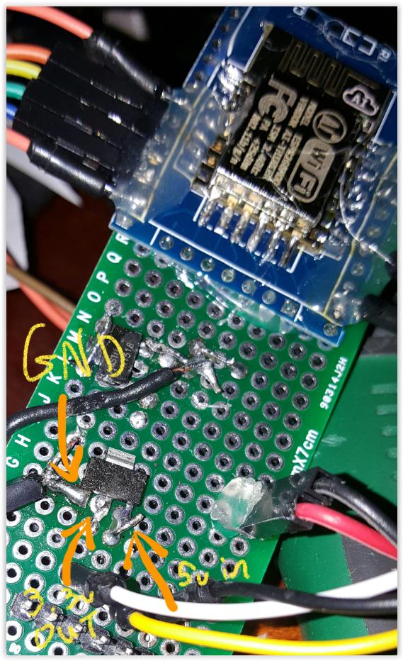
And also my breadboard:

fj4pj.jpg


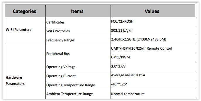
And what I have it connected to (ESP8266 ESP-12f) this is its document stating above 80mA average:

jBKo2.png

 
Last edited:

Harald Kapp

Moderator
Moderator
Nov 17, 2011
13,719
Joined
Nov 17, 2011
Messages
13,719
The -3.3 Version has a fixed output of 3.3 V. It is not adjustable.
You didn't use the required output capacitor (see datasheet, 'stability', figure 1). Your regulator possibly oscillates which shows as an erratic output votage in the DC range of your voltmeter.
 

(*steve*)

¡sǝpodᴉʇuɐ ǝɥʇ ɹɐǝɥd
Moderator
Jan 21, 2010
25,510
Joined
Jan 21, 2010
Messages
25,510
According to its documents it says its either a fixed or adjustable version?

Well, that's a fixed one. 1117-ADJ (or similar) would be the adjustable one.

Am I missing something here? This must be the adjustable version since I can not just hook it up and expect 3.3vdc to come out?

Well, you should, but I note that you don't have either the input or the output capacitor as specified in the datasheet, and I'm not sure you can reliably push them into a breadboard and expect a good connection. Try soldering a short section of bare wire to each pin and pushing that in.

As an aside, I note that your soldering is a bit messy. You probably need to put in a little more practice.
 

StealthRT

Sep 4, 2010
146
Joined
Sep 4, 2010
Messages
146
i dont have any capacitor on hand so is there any combine resistors I could you to get what i need for the input? Does the fixed version need anything on the output?
 

graemeian

Oct 2, 2014
14
Joined
Oct 2, 2014
Messages
14
Think of your regulator as cruise control on a car. When the wheels on the car are off the ground, the control will hunt for the specified speed possibly very wildly. You voltage regulator may also be hunting wildly for the correct voltage. You definitely need a capacitor(s). Remember, capacitors do not like change. The capacitor becomes a conductor when the voltage across it changes. Your circuit is well out of tune without the capacitors. Buy a bag of random capacitors for a buck at the same place you bought the stuff in the picture. Good Luck.
 

Harald Kapp

Moderator
Moderator
Nov 17, 2011
13,719
Joined
Nov 17, 2011
Messages
13,719
i dont have any capacitor on hand so is there any combine resistors I could you to get
A capacitor is a capacitor not a resistor.
You'll need to get the required capacitors.
Buy a bag of random capacitors for a buck at the same place you bought the stuff in the picture.
I recommend you buy the ones that are specified in teh datasheet, not random ones
 

(*steve*)

¡sǝpodᴉʇuɐ ǝɥʇ ɹɐǝɥd
Moderator
Jan 21, 2010
25,510
Joined
Jan 21, 2010
Messages
25,510
Can I not use some resistor's to drop the 5vdc down to 3.3vdc?

You could, but it would be some combination of vastly inefficient and not providing the correct voltage.

These three terminal regulators are incredibly easy to use, do the job well, and I'm pretty sure you've made a trivial but fundamental mistake.

Have you tried what I suggested to allow you to breadboard it better (wires on the pins)?
 

Audioguru

Sep 24, 2016
3,656
Joined
Sep 24, 2016
Messages
3,656
Two resistors in series from +5V to 0V will make +3.3V only when there is no load current. Load current will cause the 3.3V to drop. A 3.3V regulator keeps the +3.3V constant when the load current changes.
 

StealthRT

Sep 4, 2010
146
Joined
Sep 4, 2010
Messages
146
Alright this is what I have to work with:

2 x .1uF 100v Stack Metal Film
2 x 1N4148TA 100v 0.2A
2 x 35v 470uF
2 x 25v 47uF 20%
2 x 35v 220uF
2 x 10v 100uF 20%
2 x 1.0uF 50v 20%

Any of these work to step it down or use for the capacitors on the AMS1117?
 

(*steve*)

¡sǝpodᴉʇuɐ ǝɥʇ ɹɐǝɥd
Moderator
Jan 21, 2010
25,510
Joined
Jan 21, 2010
Messages
25,510
I'd probably put a 47uF on both the input and the output. Having both a 47uF and a 0.1uF in parallel on both the input and output is best, but I doubt you'd notice the difference.
 
Top