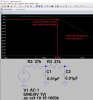
So would I, but it is unlikely that the PWM frequency is high enough to achieve that with a simple RC filter, that is why I am going for telephone quality. A 15 KHz cutoff would likely require a multi-pole active filter, as I had observed earlier in the thread. The OP does not know what the PWM frequency is, which would help a lot.
Bob