Maker Pro
Maker Pro

Arduino Resets -- Why?

RobG

Mar 10, 2021
4
Joined
Mar 10, 2021
Messages
4
I’m a mechanical engineer who rekindled my interest in electronics. I started a modest project, and I think I’m stuck on a couple small points.

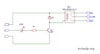
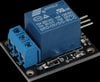
The project uses an Arduino as a smart timer which periodically activates a 12V car horn via an relay module based on the “SRD-12VDC-DL-C”. Power is supplied to the system from a 12V wall wart. The 12V is dropped to 5V via an LM7805 which feeds the Arduino and the relay relay/horn (See the diagram). That’s it! But I have a couple problems:

1. At times, when the car horn sounds, the Arduino resets. The power supply can do up to 6A and I was able to measure that the horn takes about 3A. The horn sounds for about a second at a time. The Arduino obviously takes much less power. Why should the horn sounding cause the Arduino to lose power? (I have no scope to prove this is what's happening.) Can this be? If so, how can it be avoided?

2. Unrelated, the LM7805 heats up, even when the horn is not sounding, and the only power is going through the system powers the Arduino. Why should this be?

Any help would be very much appreciated. Thanks in advance!

Diagram.jpg
 

bertus

Moderator
Nov 8, 2019
3,322
Joined
Nov 8, 2019
Messages
3,322
Hello,

Is the relays module not 12 Volts?
Arduino relays 12v.jpg
Also, what are the values of the capacitors?

Bertus
 

kpatz

Feb 24, 2014
334
Joined
Feb 24, 2014
Messages
334
As Bertus asked, what are the values of the capacitors? The reset is probably due to inductive noise from the horn, or a voltage sag depending on how much load the horn puts on the power supply.

7805 is a linear regulator, meaning whatever voltage (actually, power) that is dropped to bring the 12V to 5V is lost as heat. The amount of heat depends on the current draw of your Arduino and relay module (I assume the relay module has a driver circuit since it has a Vcc pin?)

If there's no driver in your relay module, you'll want a flyback diode across the relay coil to protect the Arduino output.

If you measure the current draw with the circuit idle, how much is it? Is the 7805 getting warm to touch, or hot? It may need a heatsink.
 
Last edited:

Minder

Apr 24, 2015
3,478
Joined
Apr 24, 2015
Messages
3,478
I tend to reverse-engineer these modules just to see exactly what the board consists of.
On an unrelated tip, it also pays to remove the small pip in the centre of the relay top.
It is a sealing pip to allow flux removal after manuf. but it also can causes contact degradation due to ionization of the relay interior when switch loads such as this, if left in place.
 

Harald Kapp

Moderator
Moderator
Nov 17, 2011
13,722
Joined
Nov 17, 2011
Messages
13,722
The relay is certainly 12 V as indicated by the relay type "RD-12VDC-DL-C". The module will have a logic compatible input (0V/5V) to be controlled by the Arduino. Therefore it needs to be connected as shown by @bertus in post #2.
The wrong connection to 5 V explains:
  • reset of the Arduino by the drop in voltage when the relay is activated from the 5 V supply.
  • heating of the 7805 by the power dissipated (7 V × current) which is rather high due to the excess current drawn by the relay module.
If there's no driver in your relay module, you'll want a flyback diode across the relay coil to protect the Arduino output.
Right. The modules I find, however, all seem to have not only a driver but are decoupled by an optoisolator, so these should be good for use with an Arduino without further measures.

@RobG : Anyway, knowing exact part numbers and values will be a great help. Appreciate if you could provide these.
 

RobG

Mar 10, 2021
4
Joined
Mar 10, 2021
Messages
4
Thank you all very much for taking on my question. I have to be away from this project for a few days, but I will report back ASAP. Again, many thanks!
 

RobG

Mar 10, 2021
4
Joined
Mar 10, 2021
Messages
4
Reporting back:

1. Capacitors: 100uF on the 12V input; 10uF on the 5V output.
2. Relay: I mis-spoke >> The module is actually based on the SRD-05VDC-SL-C (see below).
3. I don't know what a driver is for a relay module. kpatz: could you please explain?
4. I did not yet measure the current draw, but the 7805 is actually hot to the touch!

I hope I did not lead anyone too astray with the incorrect relay callout.

Is it still possible that there is a drop in voltage to the Arduino?

Where should I put the flyback diode, between the 7805 and the Arduino?

Many thanks, as always.

Rob

Relay.jpg
 

kpatz

Feb 24, 2014
334
Joined
Feb 24, 2014
Messages
334
The capacitors seem to be correct. It wouldn't hurt to add a 0.1μF capacitor after the 10μF one on the 5V side.

The SRD-05VDC-SL-C is the part number of the relay on the module. Do you have a part number or specification for the module? Where did you get it?

When I say driver, I mean the additional circuitry on the relay module. At least a transistor and the flyback diode, which I can see in the pic of the module you posted.

Measuring the current draw would help determine the heat issue with the 7805. If you could measure the current with the relay de-energized, as well as energized (you can disconnect the horn), that will help us determine the number of watts are being dissipated, and if it seems excessive, or if you just need to add a heatsink, or use a different regulator.

Does the Arduino board have its own regulator, or does it require a 5V supply? Arduino boards I've seen usually have an onboard regulator and can take 6-20V on the barrel connector or Vin pin. They also draw around 200mA which is probably what's causing your 7805 to run hot. But... you may not need the 7805 at all if your Arduino board has the barrel connector.
 

Bluejets

Oct 5, 2014
6,922
Joined
Oct 5, 2014
Messages
6,922
1. Add a couple of 0.1uF ceramics on both sides.
2. Relay , if this type below(cannot see on your photo) already has a freewheeling diode.
3. If above then already has a driver transistor (Q1)
4. Something not right if the regulator is hot........
the voltage difference will have a lot to do with it, perhaps look at using a buck converter instead.

Highly likely your Arduino is dropping out (resetting) due to brown out.
Where the voltage dips due to improper regulation or electrical noise, which the horn, due to it's construction (vibrating points) will be one of the worst sources one can get.
Because of this. you may even need to filter the 12v to the Arduino circuitry and perhaps even a choke. (ferrite ring with the supply lines wrapped through)
 

Attachments

  • sRD.jpg
    sRD.jpg
    19.3 KB · Views: 10
  • BuckConverter.jpg
    BuckConverter.jpg
    173.5 KB · Views: 7
  • KY-019.jpg
    KY-019.jpg
    99.2 KB · Views: 7
Last edited:

Harald Kapp

Moderator
Moderator
Nov 17, 2011
13,722
Joined
Nov 17, 2011
Messages
13,722
Both driver and diode seem to be present:
upload_2021-3-12_6-12-56.png

An alternative to decouple the relay from the Arduino's power supply; power the Arduino from 12 V. via the barrel connector. Thus a drop in 5 V due to switching of the relay will affect the 12 V considerably less and even if there is a dip in the 12 V line, there is enough headroom to keep the Arduino's internal 5 V stable.
 

RobG

Mar 10, 2021
4
Joined
Mar 10, 2021
Messages
4
Hello, all. I have some information to share..

It seems that the LM7805 heats up quite a bit when the relay coil is energized. The relay module draws 60-70mA when energized, as opposed to 3mA when not. So by choosing my input and the NO/NC judiciously, I can draw far less current 95% of the time. In this case the LM7805 is only a little warm.

Regarding the Arduino powering down, that issue seems to have disappeared. . . leading me to believe that I was doing something wrong all along, though exactly what I'm not sure. I expect I'll bump into this again!

Thank you all for so much help!

Rob
 
Top