Maker Pro
Maker Pro

Atari Punk Console propblems

fundash

Jul 16, 2010
8
Joined
Jul 16, 2010
Messages
8
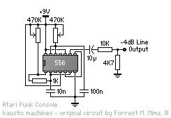
Hello everyone, I have built an atari punk console using this schematic:
atari_punk_console_schem_556.JPG


Unfortunately, it does not seem to be working at all. When turned on, you here an initial click and nothing else. There is one narrow spot where it generates white noise. here is the circuit board:

photo00001jn.jpg

photo00002l.jpg
 
Last edited:

shrtrnd

Jan 15, 2010
3,876
Joined
Jan 15, 2010
Messages
3,876
Double check all of your components, recheck all of your connections.
Have you got the ground of your circuit to the ground of your output.
How critical is the balancing of the 470K pots. Looks like one might be a linear taper, and the other one an audio taper.
Even though you 'know' you wired this correctly, you're probably going to find your
problem in your assembly of the circuit.
 

(*steve*)

¡sǝpodᴉʇuɐ ǝɥʇ ɹɐǝɥd
Moderator
Jan 21, 2010
25,510
Joined
Jan 21, 2010
Messages
25,510
One very obvious problem is that you have not removed the strips between the pins of the IC. Thus pin 1 is connected to pin 14, 2 to 13, 3, to 12, etc., etc.

There are also no other breaks in any of the strips, so you may have inadvertently connected other parts of your circuit.

In addition you're using way too much solder, and you should try to fold the leads over less (not at all is best, but if you need to keep them in place just splay the leads a little).

Check out this site. I still think he's using too much solder, but it's a lot better. Notice how he cuts the tracks.

Here is a page that shows some bad soldering and some better soldering. Yours looks more like the former. Aim for the latter.

There are many tutorials on the net, but the basic technique is to have a little solder on the tip of the iron (enough that it looks nice and shiny, but not dripping off). Hold the tip against both the lead and the pad for a second or two, then apply a small amount of solder to the wire and the pad, near where the tip is touching them (or to the point where it is touching them). You only need a very little, enough that the pad and the wire gets a nice even coating and the hole is obscured. The final joint should look more like a ski slope coming down from the wire to the board than a boulder on the board with the wire growing out of it.
 

serious coinage

Mar 26, 2011
13
Joined
Mar 26, 2011
Messages
13
Also, next time you build a circuit, it's often a good idea to test it on a solderless breadboard, so you can be sure that the circuit design works and none of your components are faulty before you solder it. It's much harder to look for problems and fix them on a soldered PCB than it is on a breadboard.

edit: Also, when soldering ICs, it's often a good idea to use a DIP socket, because if you solder in the DIP socket and then plug in the IC, there's no chance of the IC being damaged by heat, and if the IC is faulty, you can just unplug it and drop a new one back in - no desoldering involved.
 
Last edited:
Top