Maker Pro
Maker Pro

Basic Pulse generation help

majoco

Nov 10, 2019
50
Joined
Nov 10, 2019
Messages
50
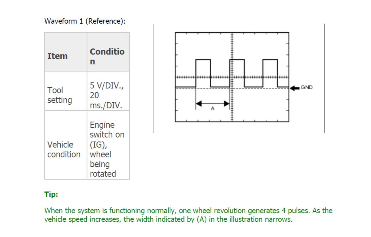
May I know the variation of pulse sequence width A?

Well, we don't know! In the sketch of the square wave it looks like the mark is slightly shorter than the space and as it's probably a mechanical magnetic pickup I guess that the M/S ratio will stay about the same even though the frequency will change, 4.2 Hz at 10mph and 42 Hz at 100mph!

A thought has struck me - is this wheel speed sensor a part of the ABS anti-skid system?
 

WHONOES

May 20, 2017
1,217
Joined
May 20, 2017
Messages
1,217
Interesting exercise - I did it a couple of times as it didn't look right. I just measured my "17 inch" wheel and its just over 26 inches diameter which makes it 163 inches circumference, 13.6 feet. and so 5280/13.6 = 388 revolutions per mile, 38,800 revs per 100 miles, 38,800/3600 = 10.7 revs per second and as there's 4 cycles per rev. then 42Hz at 100 mph! Probably the circuit will trigger on the leading edge as shown on the 'scope drawing, so I would doubt whether you need to preserve the 1:1 mark/space ratio.

Which leads me to another interesting question - when you're going down the road at 100mph, which part of your car is going fastest?

I think you sums a little off. To calculate the circumference you must multiply the diameter by PI. In you instance, your wheel circumference should be 26 x 3.142 which = 81.7".
 

majoco

Nov 10, 2019
50
Joined
Nov 10, 2019
Messages
50
You're right! Brain fade! I used pi.2D - should have thought pi.D. The end result is the frequencies are doubled, 100mph = 84Hz, 10mph = 8.4Hz - apologies to all.
 

majoco

Nov 10, 2019
50
Joined
Nov 10, 2019
Messages
50
Now there's interesting......

ALT codes! ALT928 prints as capital pi in some scripts, ALT960 prints a lower case pi, but not on this forum screen! Also found that ALT937 print a nice 'ohms' omega!
 

Rangers77

Oct 21, 2019
2
Joined
Oct 21, 2019
Messages
2
I have a speedometer/instrument cluster from a car that I am doing some bench tests on. I've got the cluster powered up by referring to the pinout diagram. I've got turn signals emulated too. However, I want to emulate speed and according to the pinout diagram, there are two speed related pins and the pins are described as:

Speed signal (Output) - Pulse generation (Waveform 1 Diagram below)
Speed signal (Input) - Pulse generation (Waveform 1 Diagram below)

I've attached the waveform diagram below. Can anyone tell me if there is a easy and cheap way to emulate this so that I can simulate speed and send this data to the cluster? I'm not sure what the difference between input and output on the cluster pins are either.

4hKVnQ7.png
 

Rangers77

Oct 21, 2019
2
Joined
Oct 21, 2019
Messages
2
Interesting exercise - I did it a couple of times as it didn't look right. I just measured my "17 inch" wheel and its just over 26 inches diameter which makes it 163 inches circumference, 13.6 feet. and so 5280/13.6 = 388 revolutions per mile, 38,800 revs per 100 miles, 38,800/3600 = 10.7 revs per second and as there's 4 cycles per rev. then 42Hz at 100 mph! Probably the circuit will trigger on the leading edge as shown on the 'scope drawing, so I would doubt whether you need to preserve the 1:1 mark/space ratio.

Which leads me to another interesting question - when you're going down the road at 100mph, which part of your car is going fastest?
 

majoco

Nov 10, 2019
50
Joined
Nov 10, 2019
Messages
50
What's the point in repeating two old threads that supposedly everyone has read with making any comment?
 

bertus

Moderator
Nov 8, 2019
3,321
Joined
Nov 8, 2019
Messages
3,321
Hello,

@majoco , When you think that a post is not suitable for the thread, you can use the report button to attract the attention of the staff.

Bertus
 

john2k

Jun 13, 2012
188
Joined
Jun 13, 2012
Messages
188
So I received the NE555 adjustable module from here: https://www.ebay.co.uk/itm/262841412289

Pin 19 and 20 on the cluster are related to speed signal. Pin 19 is speed output and Pin 20 is speed input. It seems like the output provides speed information to other ECU's that need the speed information. According to the manufacturers documentation it says:

  1. The instrument cluster meter CPU receives vehicle speed signals.
  2. The vehicle speed sensor detects the voltage that varies according to the vehicle speed.
  3. The ABS & traction actuator assembly supplies power to the vehicle speed sensor.
  4. The ABS & traction actuator assembly detects vehicle speed signals based on the pulses of the voltage.
  5. The ABS & traction actuator assembly transmits vehicle speed signals as pulses to the instrument cluster meter CPU.
  6. The instrument cluster meter CPU calculates the vehicle speed converting 4 pulses to 1 revolution.
However, when I connect a multimeter's positive probe to pin 20 and negative probe to the instrument clusters metal body, I get a voltage reading. So I'm a little confused, if this is giving a voltage then I dont think i can supply a pulse votage to it can i? There are a few other pins on the cluster that provide a voltage and when you ground those wires with certain resistors they perform a task on the cluster.

Any ideas?
 

majoco

Nov 10, 2019
50
Joined
Nov 10, 2019
Messages
50
What are you using to measure the voltage? A DMM with an input impedance of 10Mohms or more? The voltage that you read on pin 20 may be going through a high-ish value resistor to maybe the base of a transistor so you would expect a voltage there - how many volts are you getting? Section 3 says - The ABS & traction actuator assembly supplies power to the vehicle speed sensor - so the wheel speed sensor is not just a simple coil and magnet - it could well be a hall effect device in which case it needs some DC power to work - the sensor output pin is often the collector of the hall effect device..

https://en.wikipedia.org/wiki/Hall_effect
 

john2k

Jun 13, 2012
188
Joined
Jun 13, 2012
Messages
188
I'm using one of those yellow digital multimeters. it's reading about 10volts. I have a small LED prewired with a resistor and if connect it to that pin 20 and ground body of the cluster the LED lights up. So means power is coming out. So if power is coming out, how do I send pulses to it to get it to calculate speed?
 

majoco

Nov 10, 2019
50
Joined
Nov 10, 2019
Messages
50
You need a simple interface from the pulse generator to the instrument cluster. Keep your resistor and LED connected to pin 20 but disconnect the other end from ground and connect it to the collector of a 2N2222 transistor. Connect the emitter of the transistor to ground and the base to a 1kohm resistor - join the other end of the resistor to the pulse gen output. Job done. The LED should pulse showing the thing is working - if not, remove the LED and your resistor and connect the collector of the 2N2222 directly to pin 20. I'm trying to avoid shorting pin 20 to ground by drawing too much current from it. The 2N2222 is taking the place of the hall effect sensor.

Clipboard02.jpg
 

john2k

Jun 13, 2012
188
Joined
Jun 13, 2012
Messages
188
Thank you @majoco I've tried to understand your diagram by re-drawing it to match what I know. Below is a pic of my drawing. But only thing I am a little confused about is the section where I put ????? Do I just put my LED inline on that wire? So, the positive of the LED wire on pin 20 and negative of the LED on the same wire? You mention a resistor too. But the resistor is it only after the transistor?

lBM4qGQ.png
 

bertus

Moderator
Nov 8, 2019
3,321
Joined
Nov 8, 2019
Messages
3,321
Hello,

A resistor can be used to limit the current into a device.
Some devices, like the leds, are current controlled and a resistor is a must to limit the current.

Bertus
 

john2k

Jun 13, 2012
188
Joined
Jun 13, 2012
Messages
188
Hello,

A resistor can be used to limit the current into a device.
Some devices, like the leds, are current controlled and a resistor is a must to limit the current.

Bertus

Oh I see, does that mean in the diagram that @majoco drew, the output from pin 20 is going to a resistor then a LED? But my LED is pre-wired with a resistor already to accept 12v. So I would just connect it inline to the pin 20 output where i drew a box with ????
 

bertus

Moderator
Nov 8, 2019
3,321
Joined
Nov 8, 2019
Messages
3,321
Hello,

Do you have specifications what signal is expecpted at pin 20 of the instrument cluster?

Bertus
 

john2k

Jun 13, 2012
188
Joined
Jun 13, 2012
Messages
188
Do you have specifications what signal is expecpted at pin 20 of the instrument cluster?

Only the picture I posted in the first post and the following information:

Pin 19 and 20 on the cluster are related to speed signal. Pin 19 is speed output and Pin 20 is speed input. It seems like the output provides speed information to other ECU's that need the speed information. According to the manufacturers documentation it says:

  1. The instrument cluster meter CPU receives vehicle speed signals.
  2. The vehicle speed sensor detects the voltage that varies according to the vehicle speed.
  3. The ABS & traction actuator assembly supplies power to the vehicle speed sensor.
  4. The ABS & traction actuator assembly detects vehicle speed signals based on the pulses of the voltage.
  5. The ABS & traction actuator assembly transmits vehicle speed signals as pulses to the instrument cluster meter CPU.
  6. The instrument cluster meter CPU calculates the vehicle speed converting 4 pulses to 1 revolution.
However, when I connect a multimeter's positive probe to pin 20 and negative probe to the instrument clusters metal body, I get a voltage reading. So I'm a little confused, if this is giving a voltage then I dont think i can supply a pulse votage to it can i? There are a few other pins on the cluster that provide a voltage and when you ground those wires with certain resistors they perform a task on the cluster.
 

bertus

Moderator
Nov 8, 2019
3,321
Joined
Nov 8, 2019
Messages
3,321
Hello,

What voltage did you get on pin 20?
Is it about the supply voltage?
It can be there is a pull-up resistor inside the unit.

Bertus
 
Top