Maker Pro
Maker Pro

Blown 2n3055 transistors

Damien

Jan 28, 2015
55
Joined
Jan 28, 2015
Messages
55
Hey guys

I'm a little stumped as I just put my power supply together which long story short consists of an lm317 driving two 2n3055 pass transistors.

These 2n3055's are rated for 15 amps each and they're paralleled so I should theoretically get 30 amp handling capacity.

I tested it out last night with a little portable drill that I butchered to have 12v leads comming off for portable work requirements.

It worked for a while so I started drilling some holes in the power supply case (timber so no chance of a short). They were only getting slightly warm when I noticed the output voltage was giving a full 30v's instead of the regulated setting I had at 14v.

Is it possible that while tightening the chuck on the drill (motor in drill only slightly moving while holding the chuck key with hand to put a new drill bit in) That I drew more than 30 amps and blew them both?

I thought these things had overload protection?

To give you an idea of my schematic it looks like the one in this link -

https://docs.google.com/viewer?a=v&...iZXR0aW5hbmV1bXJ5cnxneDo1ZWMyNWUzNTliYWYyMDRl

Except for the control circuitry is an lm317 instead of the lm723 I.C shown in this schematic.
I also don't have a diode going from the emitter back to the collector, I'm not sure why they put this here? o_O Should I also have a resistor for each of the bases of these pass transistors to help with load sharing? Before blowing they both were getting a tiny bit warm with a 2 amp load at 12v after about 2 minute but not hot by any means.

Any help would be appreciated thanks in advance

Ordered some 30 amp automotive fuses off ebay and some new 2n3055 transistors.

Regards -

Damien
 

(*steve*)

¡sǝpodᴉʇuɐ ǝɥʇ ɹɐǝɥd
Moderator
Jan 21, 2010
25,510
Joined
Jan 21, 2010
Messages
25,510
Firstly, a 723 is not a great chip to use. It's ancient and pretty tricky to use correctly.

Secondly your circuit shows where 0.1 in resistors should go, but you've left them out. Without these, one transistor can take a great proportion of the load and fail. You really need them.

Thirdly, it is unlikely that you'll get 15A out of one of these transistors without exceeding some other maximum rating.

Fourthly, you don't mention the input voltage. This is critical for a number of reasons.

Fifthly, I assume you have these transistors connected to a large heatsink.

Sixthly, a 2N2222 can't provide enough base current and has also possibly failed.

Seventhly, your circuit has no current limit. If your input source can provide a large current, this circuit will try to provide it to any load which demands it.

Take a look at circuits based on LM317s and series pass transistors. This too has no current limit. You need to go to additional effort for that.
 

cl10Greg

Mar 20, 2014
25
Joined
Mar 20, 2014
Messages
25
Steve provided a lot of good points. My additional comments are you have to remember temperature degradation and the non ideal world. You need to make sure you have a beefy transistor to supply base current as soon as possible. You want to get those transistors out of the active region where they heat very quickly. Also, since you are using only a single driver to the bases, they may not all be getting the same drive and may not work exactly at the same time (real world tolerances). This could cause the load to heat up one over the others a bit more. You should have a resistor to each base because currently it's just power draining into whatever base gap forms first. The diode is used for flyback protection. Depending on your load, a reverse voltage (EMF) can be present and can cause the transistors to fail. You see these often in motor controls (look up any H-bridges). Transistor ratings are tricky because most of them are talking in terms of the junction and to keep the junction cool enough from failing at those levels needs a big heatsink or active cooling. You will see a lot of marketing goons claiming a TO-220 transistor can run 50A through those little legs.
 

Damien

Jan 28, 2015
55
Joined
Jan 28, 2015
Messages
55
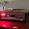
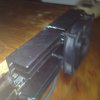
Thanks for your input guys. As you can see I have them mounted on large heat sinks (it's actually duel rail) I'm using the heat sink as the collector conductor (2 transistors per rail & heat sink cut in half down the middle as you can see). I can understand how back emf could be a problem with particular loads so will add these diodes. I imagine the spikes would carry alot of current depending on the load?
The load in question was limited to 14 volts.

I have a few questions.

* how big should the diodes to handle flyback currents be?

* What value resistor should I put inbetween the output of lm317 & the base of the 2n3055's?

* How do I implement a current control circuit? I have read on some forums that people suggest starting all over again as it's better to implement the current control rather than add it on to an existing circuit.

Appreciate your help. Thankyou.

- Damien
 

Attachments

  • 006.JPG
    006.JPG
    137.6 KB · Views: 429

Damien

Jan 28, 2015
55
Joined
Jan 28, 2015
Messages
55
Oh one question I forgot to ask -
I have a separate circuit running mounted on the same protboard. It's a l7812cv voltage regulator. It's wired up correctly as I use these quiet a bit for u.s.b chargers (l7805cv for example). I have this regulator in service and have it wired to some indicator led's on the front panel as well as the meters and also to the rear 12v cooling fans. I have a small capacitor (1000uf 16v) running after the regulator just to smooth out any noise as I thought the meters may be a bit fussy.

Anyhow - I have this stange thing happen where when I turn the power supply on at the a.c switch, the meter only shows volts and is really dim (it's meant to show volts and amps as it's a combined meter) But if I flick the power off and on again really quickly it comes online and works great.

Would putting a separate switch between main capacitors and the 12 volt regulator to run the 12v regulator fix this problem? Could the regulator itself be faulty? I just found the fact that turning the mains off and on again temporarily fixed this problem. Could the meter have protection circuitry built in where if it doesn't see 12v straight off the bat it won't operate properly & perhaps charging up that 1000uf cap between the regulator and the meter would stop this from happening? Should I remove the cap?

I know this is a completely different problem to the one I am experiencing with the 2n3055 pass transistors. On that note , Steve I did have a look at several circuits on the net implementing the lm317 with 2n3055 pass transistors and they look very similar to the one I'm running. Bear in mind that the circuit diagram I posted is not mine, it's just one I went off and the 723 chip is betinna's not mine. Betinna posted a you-tube vid of her power supply on youtube, quiet impressive for a linear design. Well, to me anyhow.

I wanted one like hers to run ham radio gear -
Here's the vid of her power supply. -


shrtrnd

Jan 15, 2010
3,876
Joined
Jan 15, 2010
Messages
3,876
Old-timer peripheral input here. (For whatever it's woth)
Back in the 1970's the 2N3055 was a pretty robust transistor. I work on a lot of 1970's era gear.
When replacing 2N3055's in the old gear, I noticed they often didn't last very long.
I talked to engineers at one of the semiconductor manufacturers years ago, and was told the newer 2N3055 dies were changed, and that the newer 2N3055s were not as robust as the original design.
I don't design 'em, that's what I was told. Opposing viewpoints exist.
I was told to replace the 2N3055's with the newer MJ15003, with is tougher than present-day 2N3055s. That's what I've been doing for many years now.
I'm not discounting any of the other good advice given thus far on this post, I'm just adding peripheral infomation.
Additionally, are you aware that those voltage regulators are made inf both TO-220 packages AND TO-3 Packages?
The TO-3 packages can handle a lot more use/abuse than the TO-220 packages. Since you're building your own power supply, I'd go for the best I could do.
Don't forget to utilize all the other good advice you've received here in answer to your questions. Just adding my two-cents worth.
 

Damien

Jan 28, 2015
55
Joined
Jan 28, 2015
Messages
55
Thanks for that shrtrnd I will rip these ones out and put some MJ15003. I might get the rest of the circuit just operational first & then upgrade the MJ's when I'm ready to put it into service. Any opinion as to why that L7812cv for the fans,meters and led circuits is dropping voltage on startup & if I turn it on an on again it powers up fine? Could the cap I am running in front of the 7812 be too big? I might post a scanned schematic of my design so it's easier to understand but can you guys kinda imagine a circuit in your head or is it easier if I provide a diagram to my specific power supply. I want it to work well (for a linear design) Don't care about looks so so much. 006.JPG 008.JPG 007.JPG on the side of the road)

- Damien
 

shrtrnd

Jan 15, 2010
3,876
Joined
Jan 15, 2010
Messages
3,876
My guess would be that the fans starting-up might be drawing an initial current surge. I don't know the value of your cap in the circuit. (I suppose it's possible tht the cap would be fully charged during your second start-up, and you
might not see the initial start-up power drop the second go-around).
I'd consider using the TO-3 Power Pkg +12V regulator, but that may not be the issue here.
 

cl10Greg

Mar 20, 2014
25
Joined
Mar 20, 2014
Messages
25
* how big should the diodes to handle flyback currents be?

* What value resistor should I put inbetween the output of lm317 & the base of the 2n3055's?

* How do I implement a current control circuit? I have read on some forums that people suggest starting all over again as it's better to implement the current control rather than add it on to an existing circuit.

The flyback voltage dissipates very quickly so it can be pretty much an power diode (TO-220) and you wouldn't need to heatsink it because of the short spike.

We know that the 2n3055 has a gain that is dependent on the load current and variest from 70 down to 5. The gain and base current is what dictates the amount of load current. So if you want to max it out at 10A and the gain is 5, you would need a 2A base current. So depending on the loads you can decide.

Current control is usually done with an adjustable regulator that uses the output as the adjustment value or with a special IC. You can search LM317 to see examples.
 

Damien

Jan 28, 2015
55
Joined
Jan 28, 2015
Messages
55
Shrrnd:

That was my guess to so I removed the cap but nope, still doing the same thing so I ripped out the regulator and swapped it for a 7805 (5 v linear regulator). I would have used a another 12v one but didn't have any lying around so just thought I'd try the 5v as I know my meters and l.e.d's will run on 5v and also the fans will too (Only at 1/2 speed but perhaps this is a good thing due to less noise and more life from the fan bearings).
Presto! Full power from the moment I hit mains switch. =) So that's that problem solved. Thanks for your input it is nice to know
(with your help) that I was on the right track with the cap being my first object of suspicion.

CL10Greg:

I want each one to max out at 15 amp and since they share the base terminal does that mean I need 4 amps into the base? o_O My lm317 delivers I think from memory is only capable of 1 amp output (I could be wrong about this I will have to double check maybe it was 1 amp without a heat sink and 3 with a heat sink. Anyhow, I was actually afraid this would be too much but from what you're saying I am getting the idea that it's not enough! Should I run like a pre amp circuit inbetween the output of lm317 an the base of the twin 2n3055's?

I currently have a 30 ohm resistor between the output of the lm317 and the base of the finals (2n3055's) in fear that I was over driving them.

I placed a 3 amp diode between emittor and collector in reversed biased position (power going from emittor to collector) for flyback voltages. Diode I have installed currently is to-220, can I get away with a smaller one or is it good insurance to oversize this a little if anything?

I believe it was flyback voltage that killed two of my transistors because it only blew when I released the trigger on my drill very quickly (it's a speed trigger). So alot of power running and then bang, nothing..Is what we have in this condition a collapsing magnetic field inducing a large current spike with nowhere to go besides though the diodes inside the 2n3055's and cooking them in an instant?

I installed the voltage spike protection diodes and walla, used drill and no more magic white smoke. =)

I'm really happy as I feel like I'm getting somewhere with this but it is still dropping alot of voltage under load. I just hope this is due to having no capacitors after the finals (I know I need about 30,000uf) but I've been studying for the last two years and havn't been able to order them but starting my new job on Monday so this will be one of the first things I invest in. two 30,000uf capacitors. (One for each rail). I am hoping that the drop in voltage is just due to the wave form being a d.c pulse that only gets more unstable under load and so the meter is just seeing an average of 0-15 volts instead of a steady flat D.C line on the oscilloscope (I'm only guessing as I don't own an oscilloscope this is definitely on the wish list though for the future). I hope that the voltage drop is just due to lack of capacitance & not just good old transformer voltage sag I'll be a little dissapointed if it is as I've seen guys on youtube draw 20 amps from the same transformer and my voltage is dropping with just a 30watt load. I'll post a picture of the transformer to give you an idea of the size. It doesn't have any numbers on it so I don't know what it is but it has two outputs. One is 13 volts and the other is a center tapped 40v line. I took the center tap and hooked it up to one side of a full wave bridge rectifier & took the outer taps & placed a diode on each one facing into the other side of the bridge rectifier. I hope this makes sense I'll post a pic just incase it doesn't. Please excuse the messyness of my work I have had to use second hand wire form 240v electric cables etc and it is not as neat as I would like perhaps I will clean it all up when it is completed.

I wish I'd marked everything out & drilled, cut holes before mounting it onto the case. You live and learn I guess.

What is everybody working on atm?
 
Last edited:

Damien

Jan 28, 2015
55
Joined
Jan 28, 2015
Messages
55
No idea on the output as this transformer has no info stamped on it apart from voltages. I'm hoping it's above 10 amps on at least one of the rails? o_O What if I ran both rails in parallel this would essentially double my current output right? If I set both rail at the same voltage with the variable regulators or would one rail sag & the other take most of the load?
Having a transformer with multiple taps has made things more complicated but just trying to make the most of what I have & utilizing it's features by incorporating a duel rail etc. I could have made it single rail & just ignored the other outputs of the transformer but I considered this to be a waste of opportunity.

From the picture below you can get a relativity for the size of the transformer against a 15 amp rectifier which I'm sure you're all familiar with. The picture also shows the way I have utilized the center tap by using diodes so create a kind of half wave rectifier going into a full wave. I'm not sure what this is called but saw it utilized in an old battery charger that I pulled apart a while ago and thought it was a clever way of getting the most current from a center tapped transformer.
 

Attachments

  • small.jpg
    small.jpg
    304.7 KB · Views: 211

Damien

Jan 28, 2015
55
Joined
Jan 28, 2015
Messages
55
Haha I've posted a few times but the further I look into this the more questions I have it's like a can of worms.

I know Shrtrnd mentioned that I should replace my 2n3055's with the newer MJ15003's but they are literally 15 times the price.
Ebay has them listed for $15 and the 2n3055's for $1. Haha.

So...for the moment it's 2n3055's or nothing.

Just trying to make sense of the 2n3005 datasheet.

CL10GREG: -

You mentioned that with 2 amps flowing into the base of the 2n3055 it will pump out 10 amps from emitter? Since these are rated at 15 amps...would this mean to get the full 15 amps out I would need 3 amperes at the base?

Since the lm317 I am driving these 2n3055's only put out a max of 1.5 amp I need another 1.5 amps to get my 2n3055's to saturate completely.

Could I just run a couple of lm317's in parallel to double the 2n3005 collector current? o_O

If the 2n3055 was a mosfet I'd be home and hosed. Is there a large mosfet that comes in the same format as the 2n3055 that I can bolt in later down the track?

Thanks for your help people. Can't be wait to be the person at the other end giving advice to newb's like me. =P
 

Damien

Jan 28, 2015
55
Joined
Jan 28, 2015
Messages
55
http://electronics.stackexchange.co...-can-i-get-more-amps-from-a-voltage-regulator

Would this be the way to go to get more current at the base of those 2n3055's? Also if I have them paralleled (The 2n3055's) Does that mean that I need a total of 8 amps to completely saturate two 2n3055's in parallel? So...6 or 8 lm317's in parallel to get the 8 amps of base current needed for the 2n3055's?

Please forgive me for using hardware from the 70's. Them 2n3055's are very temping to buy at $1 each but I am slowly learning that you get what you pay for, even with electronics hey.

A funny thing, With these 2n3055's I have the supply voltage from the bridge rectifier going to the collector and the emitter going to the load. Am I doing this wrong as all the schematics I have looked at say to drive the load before the collector and to ground the emitter but I tried this & it didn't work.
 
Last edited:
Top