Maker Pro
Maker Pro

Bypassing TV's internal speakers to home-made aux input

AnalogKid

Jun 10, 2015
2,893
Joined
Jun 10, 2015
Messages
2,893
Don't do it! If your TV does not have a power transformer
There is no IF here. The two big yellow things on the right side pc board with writing on them are power transformers. Note that the cross-hatched marking (the isolation barrier) runs right underneath them between the primary and secondary pins.

Drive to the speakers is almost certainly Class-D and bridged, there is no electrical hazard.

ak
 

Audioguru

Sep 24, 2016
3,656
Joined
Sep 24, 2016
Messages
3,656
We are guessing that the speakers in the TV are driven with "bridged" amplifiers because joining the black speaker wires to the stereo headphones caused problems but using a single channel without joining the black wires was fine.

A bridged output has an audio power amplifier driving each of the four speaker wires but the amplifiers for each channel have opposing phase causing their signal voltages to a speaker to be double what a single output would be, creating almost 4 times the power. If the red wire goes up to +10V then the black wire goes down to 0V, then the red wire goes down to 0V and the black wire goes up to +10V. With no audio all the wires have +5V so that the speakers have no DC voltage across them without using coupling capacitors. The two red wires have stereo signals like an normal amplifier but they are at +5V so to use them with headphones connected to ground then coupling capacitors must be used to block the DC. Then the TV's black speaker wires are not joined together and they are not connected to the headphones. The ground wire of the headphones is connected to the amplifier ground (0V) instead. The ground wire of the headphones is common to both earphones and connects to the "sleeve" of the headphones plug. The plug has 3 connections: tip for one channel, ring for the other channel and sleeve for the common ground.
Joining the black wires is shorting the outputs of two power amplifiers together that is bad.
 

Alec_t

Jul 7, 2015
3,590
Joined
Jul 7, 2015
Messages
3,590
If the red wire goes up to +10V then the black wire goes down to 0V, then the red wire goes down to 0V and the black wire goes up to +10V.
This pre-supposes there is a single-polarity supply. I've no experience with modern TVs, but do all TVs have that for the audio stages, or could there be a dual-polarity supply?
 

Audioguru

Sep 24, 2016
3,656
Joined
Sep 24, 2016
Messages
3,656
Every TV is different but many modern audio products use bridged amplifiers. There is no need for a dual polarity supply for a bridged amplifier because the speaker has no DC across it. Most car radio amplifiers are bridged and they do not use a dual polarity supply. Texas Instruments make many bridged amplifier ICs and they do not need a dual polarity supply.
Many ordinary amplifiers or opamps with a single positive supply and 0V do not need a dual polarity supply because they have the amplifier biased at half the supply voltage and use input and output capacitors to pass the AC signals but block the DC.
 

hedgehog90

Sep 1, 2012
29
Joined
Sep 1, 2012
Messages
29
As much as I try to understand what everyone's saying, I'm afraid most of this whizzing over my head, chaps.
What size capacitors would you recommend, Audioguru? Or do you think the ground loop isolator on its own should do the trick?
 

Audioguru

Sep 24, 2016
3,656
Joined
Sep 24, 2016
Messages
3,656
The value of a coupling capacitor depends on the speaker impedance it feeds and the lowest frequency you want.
The formula is C= 1 divided by (2 x pi x frequency x impedance) so assuming your headphones are 32 ohms and you want to hear low frequencies down to 30Hz the capacitor value for each of the two stereo channels is 167uF, use 220uF.
 

hedgehog90

Sep 1, 2012
29
Joined
Sep 1, 2012
Messages
29
25V or 50V? I'm guessing it doesn't really matter, I got some 50V ones.
 
Last edited:

Audioguru

Sep 24, 2016
3,656
Joined
Sep 24, 2016
Messages
3,656
with an output of only 3W the output voltage is puny so 16V, 25V or 50V capacitors would be fine.
 

Alec_t

Jul 7, 2015
3,590
Joined
Jul 7, 2015
Messages
3,590
If a single-polarity supply is used, as AG says, then the + terminal of the capacitor should connect to the speaker's red wire.
 

Audioguru

Sep 24, 2016
3,656
Joined
Sep 24, 2016
Messages
3,656
The + wire of very old capacitors was marked "+" but modern capacitors have the - wire marked "-----".
 

hedgehog90

Sep 1, 2012
29
Joined
Sep 1, 2012
Messages
29
The ground wire of the headphones is connected to the amplifier ground (0V) instead.

I'm using 2 RCA leads. Just to clarify, each RCA red wire should connect to the + speaker terminals via a coupling capacitor, while the RCA ground wires should connect to ground (0V).
Is this correct?

Do I need to hunt around for a ground spot on the board to connect to RCA ground wires? If so, how do I do that with a multimeter?

Maybe you can spot a likely ground terminal on this high-def image: https://spares2repair.co.uk/panason...PY4rnE6jGjQT8D6LEk5YTuyPV04PsvcaAm4IEALw_wcB&
 

Audioguru

Sep 24, 2016
3,656
Joined
Sep 24, 2016
Messages
3,656
I was thinking about scraping off some green to expose some copper then I saw this solder joint:
 

Attachments

  • probable ground.jpg
    probable ground.jpg
    53.7 KB · Views: 165

hedgehog90

Sep 1, 2012
29
Joined
Sep 1, 2012
Messages
29
The way I'm determining ground is by putting one probe of a multimeter to the negative speaker terminal and using the other probe to find the point with least resistance.
The solder point you pointed out, screw mounting points, etc. measure ~510 ohms. There is no spot that measures less than that.
Are these suitable ground points?
 

Alec_t

Jul 7, 2015
3,590
Joined
Jul 7, 2015
Messages
3,590
The way I'm determining ground is by putting one probe of a multimeter to the negative speaker terminal
That terminal is not at ground potential, but the RCA outer contact should be (as AG noted).
 

Alec_t

Jul 7, 2015
3,590
Joined
Jul 7, 2015
Messages
3,590
Put one meter probe on the RCA outer (assumed to be circuit ground) and poke around with the other meter probe. Or trace the circuit back from the earth connection (if there is one) at the mains input.
 

BobK

Jan 5, 2010
7,682
Joined
Jan 5, 2010
Messages
7,682
Put one meter probe on the RCA outer (assumed to be circuit ground) and poke around with the other meter probe. Or trace the circuit back from the earth connection (if there is one) at the mains input.
Huh? He is trying to determine what to connect to the RCA ground terminal, which he added.

Bob
 

Audioguru

Sep 24, 2016
3,656
Joined
Sep 24, 2016
Messages
3,656
The way I'm determining ground is by putting one probe of a multimeter to the negative speaker terminal and using the other probe to find the point with least resistance.
The solder point you pointed out, screw mounting points, etc. measure ~510 ohms. There is no spot that measures less than that.
Are these suitable ground points?
You did not understand that the speaker amplifiers are bridged amplifiers. A bridged amplifier is two amplifiers, one amplifier for each speaker wire. Then the red speaker wire has one amplifier and the black speaker wire has another amplifier. The amplifiers are connected out-of-phase so that the signal voltage swing is double what it is if only a single normal amplifier and ground is used. Since Power= (voltage squared) divided by the speaker impedance then the power is almost 4 times the power of a simple single amplifier and ground.
Connecting your headphones to the speaker wires cause you to short the outputs of the amplifiers for the black speaker wires together which luckily did not destroy them.

I selected the solder joint of the metal bracket that holds the RCA jacks as the ground because it usually is grounded as an interference shield and is connected to the largest expanse of copper on the pcb.
 

hedgehog90

Sep 1, 2012
29
Joined
Sep 1, 2012
Messages
29
I haven't received the capacitors yet but I've just tested out the Ground Loop Isolator.
The results are rather interesting!
It fixed the hissing problem and it seemed to sound alright on headphones. Still not as good as the built-in headphone socket, but much better than before.
But I wanted to inspect the quality of the sound better, so I plugged in a line out to a laptop and recorded 60 seconds of my favourite music (I hope the rest of you appreciate a bit of Radiohead)

--------------------------------------------------------------------------------

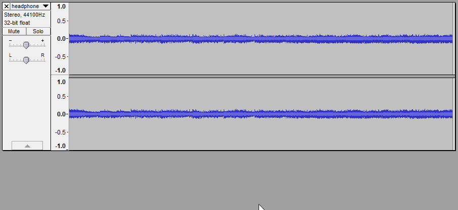
Connected via the internal speaker + and - wires, speaker volume set to 8 out of 100.
This is what it produced:

Click Here To Listen

Mo3FY50.png


--------------------------------------------------------------------------------

Connected via the built in headphone socket, headphone volume set to 20 out of 100
This is what it produced:

Click Here To Listen

LlrghyG.png


--------------------------------------------------------------------------------

Fairly different.
Strangely, they didn't sound that different through my headphones, I assumed they were about the same volume.

Remember, I eventually plan to use some old PC speakers with the TV, which has an amplifier of it's own. I figured I'll set the PC speaker volume to max and rely on the TV remote for volume adjustment.
It's an odd solution, sure... but let's ignore that aspect shall we?

Audioguru, you mentioned using a 220 ohm resistor in series to reduce the maximum loudness.
What would you suggest now?
 
Last edited:

Audioguru

Sep 24, 2016
3,656
Joined
Sep 24, 2016
Messages
3,656
The hiss disappeared because the Ground Loop Isolator cut off the highest frequencies.
It is difficult to hear the quality of the sound since the "rock" music has a high amount of intermodulation distortion (fuzz).

I don't know how much too loud are the headphones when connected to the speaker outputs with the ground loop isolator. Try some series resistor values to reduce the maximum level so that your hearing and headphones survive.
 
Top