.
Sir Archie Moore . . . . . . .
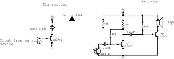
Didn't you have the rest of the accompanying explanatory text with the schematic ?
NOT much there, so don't expect much.
http://www.free-circuits.com/circuits/audio/104/laser-communication-system
Yes that is a photocel which is the receptor of the audio modulated laser beam from the left.
Its audio is then amplified by the two transiostors to the right, to then activate the systems speaker.
Of which, we should not expect a wall shattering sound level from.
Specs and supplier for that photo cell is here :
http://www.mouser.com/ds/2/427/bpw16n-109596.pdf
If I were building that circuit I would start off with a much lower powered transmitter, in the order of initially using a common RED led connected to an audio sources output and then
tune in to get a constant banter of speech such as a talk show to drive it.
That would then let you "see" the speech peaks and lulls to set up to . . . . . akin to using a radio announcers VU meter.
Then place the LED near the photocell to experience the first reception of sound and play around with backing away to evaluate its range capability.
Back away until you can just barely hear the sound.
THEN . . . .you toy with the overbiased base connections of both transistors.
Start with placing a 10 K linear variable trimpot on the base of the Q7 . . . . . . HEY ! . . . . Q7 . . . . .Q7 . . . . . .maybe the reason for its deficiency, is that he forgot to show us how he used
his Q2 thru Q6 transistors ? Ha Ha Ha.
Rotate the pot fully Counter clockwise and note the side terminal that would leave the pot wiper being against.
That terminal gets connected to ground. The center wiper connection goes to the base of Q7 transistor.
Power up again and initially you will have no sound, then as you rotate the wiper clockwise your sound will reappear and you adjust the pot for the best sound.
Next you power down and hook up another 10 K linear variable trimpot on the base of the Q8 output transistor .
Same procedure on its hook up as with the other.
Adjust it also for the best sound level and quality with the use of the LED transmitter being positioned to that distance of just intelligible sound reception.
Then you go back to the 1st trim pot and see if audio can be improved upon.Then adjust the 2nd trim pot the same way.
By this time you will have optimized for "middle of the road" biasing on both transistors, to the best as can be expected.
They are now responding to a weak input signal and then have biasing latitude to increase the gain progressively as input increases.
As it was, the audio amplifier circuitry was either needing quite a hefty signal input to get audio output or else going into clipping and saturation in a hurry from the incoming signal.
If that receive portion is working good then, with the ncorporation of a collimating lens lens in front of, and matching its focal point, to the photocell apex, I could see muuuuucccccch greater range possibility than that party of the first party ever expected . . . . with the final use of the audio modulated laser
BUT on the laser transmitter, incorporate those other suggested drive procedures until you can see the production of good voice modulation swings on a white sheet of paper.
73's de Edd
.
") !
!