Maker Pro
Maker Pro

Can I get this scale to work again?

noquacks

Jun 26, 2013
122
Joined
Jun 26, 2013
Messages
122
People,

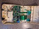
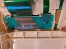
Have 2 photos attached, of a precision scale. 20 years old. It started to behave badly by displaying some garbled numbers/letters on the LED display upon pushing the ON button. So I removed theback, and just gave a visual for obvious burn marks, etc, without much knowledge at all about electronics. Then I closed the backing to the box, and pushed tyhe ON button, now nothing at all shows up on the LED display- blank, nothing.

Not sure if my pictures may help you determine what I should go after, if anything, and I am not that hopeful that it can be fixed. Where would you start? I already checked to see if the transformer was reading 12V at the terminal.

Thanks, people.
 

Attachments

  • IMG_20230106_172331.jpg
    IMG_20230106_172331.jpg
    418.8 KB · Views: 13
  • IMG_20230106_172314.jpg
    IMG_20230106_172314.jpg
    448 KB · Views: 12

kellys_eye

Jun 25, 2010
6,514
Joined
Jun 25, 2010
Messages
6,514
Usual failure points are aroud the ribbon cable and connection between the LCD itself and the circuit board.

Remove the display and show us how the LCD glass is attached to the PCB - quite often it is via the use of 'zebra connectors' that suffer corrosion and/or simple dirt/grease contamination that can stop the display working quite easily.
 

noquacks

Jun 26, 2013
122
Joined
Jun 26, 2013
Messages
122
Usual failure points are aroud the ribbon cable and connection between the LCD itself and the circuit board.

Remove the display and show us how the LCD glass is attached to the PCB - quite often it is via the use of 'zebra connectors' that suffer corrosion and/or simple dirt/grease contamination that can stop the display working quite easily.
Thanks, Kelly! Will try to follow your steps, hopefully I can unscrew the display rectangle, then post a few pictures. I hope I can interpret your instructions correctly.
 

noquacks

Jun 26, 2013
122
Joined
Jun 26, 2013
Messages
122
I unscrewed 2 screws and flipped back the display , exposing the 2 ribbon connections. Does this help? 2nd picture is probably a better view. Thanks in advance!
 

Attachments

  • IMG_20230107_083054.jpg
    IMG_20230107_083054.jpg
    178 KB · Views: 13
  • IMG_20230107_084748.jpg
    IMG_20230107_084748.jpg
    324.1 KB · Views: 12

noquacks

Jun 26, 2013
122
Joined
Jun 26, 2013
Messages
122
Another picture, after removing the black plastic trim around the LED, exposing the ribbon connection. Hope that helps a bit more.
 

Attachments

  • IMG_20230107_090723.jpg
    IMG_20230107_090723.jpg
    400.5 KB · Views: 9

kellys_eye

Jun 25, 2010
6,514
Joined
Jun 25, 2010
Messages
6,514
Careful! The attachment of ribbon cable to the display board is delicate and often the cause of display issues. I can't see (form your pictures) how the actual LCD connects to the board - this is where the 'zebra strip' is potentially located - the white strip under the display?

You should also check the location of the ribbon cable at the main circuit board - it appears to be 'away' from the board as if the socket itself has been pulled away.

Power the display and use gentle, well spread, pressure at the LCD panel itself to compress the LCD against the (assumed) zebra strip and see if the digits reappear. Do the same for the ribbon cable but VERY carefully as the connection at the LCD board is VERY fragile....
 

Bluejets

Oct 5, 2014
6,922
Joined
Oct 5, 2014
Messages
6,922
With the amount of speckily rust/corrosion deposits around inside the case and on some of the screw heads, likely a corroded connection on the LCD.
 

noquacks

Jun 26, 2013
122
Joined
Jun 26, 2013
Messages
122
I can't see (form your pictures) how the actual LCD connects to the board - this is where the 'zebra strip' is potentially located - the white strip under the display?
Look at my post #4, picture on right, LCD display is on the right, attached to the ribbon, then goes to the white zebra strip, into the green board. Does that help? (meanwhile, I am trying what you said about powering up, carefully.....)
 

noquacks

Jun 26, 2013
122
Joined
Jun 26, 2013
Messages
122
I plugged it in, pushed the power button a few times, gently giggled a few areas, and nothing happens. I fear I am now stuck. Any more options you can think of?
 

noquacks

Jun 26, 2013
122
Joined
Jun 26, 2013
Messages
122
I just thought- I was turning the power button on without the below steel plate. Could that be why I will not get any led display? It is full of rust, and so I am going ton sand it all off, and try again. That steeel plate appears to "ground" parts of the board together, and without that no way to ever get a display, right? Or wrong?
 

Attachments

  • IMG_20230108_110755.jpg
    IMG_20230108_110755.jpg
    495.6 KB · Views: 1

noquacks

Jun 26, 2013
122
Joined
Jun 26, 2013
Messages
122
No difference- still no power displaying. May be a dumb question, but I am doing all this without the weighing platform plugged into the box- does it need to be attached (it attaches with a 6 pin connector, if that matters)? The platform is at work, and I am at home currently.
 

dragon

Oct 31, 2022
248
Joined
Oct 31, 2022
Messages
248
That's a bit unlucky, should've left it unopened it seems. my condolences.
 

kellys_eye

Jun 25, 2010
6,514
Joined
Jun 25, 2010
Messages
6,514
Given the power switch is 'software' controlled (from the tactile push button on the from panel) you have to be sure that the signal is reaching the processor else it will never power on. There is a separate ribbon cable from the push button board (the narrower ribbon) - follow it back to the push buttons and open that area up (show us the results).

Commonly those tactile buttons fail entirely but you can 'simulate' their operation by shorting two of the ribbon 'lines' - which two could be determined by following the traces on the rear of the switching membrane.
 

noquacks

Jun 26, 2013
122
Joined
Jun 26, 2013
Messages
122
Given the power switch is 'software' controlled (from the tactile push button on the from panel) you have to be sure that the signal is reaching the processor else it will never power on. There is a separate ribbon cable from the push button board (the narrower ribbon) - follow it back to the push buttons and open that area up (show us the results).

Commonly those tactile buttons fail entirely but you can 'simulate' their operation by shorting two of the ribbon 'lines' - which two could be determined by following the traces on the rear of the switching membrane.
There is still hope, Kelly!! So, I understand about the push button , and shorting the lines. I now need to make sure I do it right (first time ever). Let me "open that area up" as you say, and send a picture or 2.........
 

noquacks

Jun 26, 2013
122
Joined
Jun 26, 2013
Messages
122
3 pictures below- on the 1st one I peeled back the heavy sticky face cover, exposing the ON button (top one). Not sure if that helps.
2nd picture- how the thin ribbon is pleated/folded back toward the connector on the board. 3rd- pulled back with the tip of a pen the folded ribbon showing the "lines" . Are these the ones you said could be shorted?
 

Attachments

  • IMG_20230109_173056.jpg
    IMG_20230109_173056.jpg
    246.9 KB · Views: 6
  • IMG_20230109_172731.jpg
    IMG_20230109_172731.jpg
    274.7 KB · Views: 6
  • IMG_20230109_172810.jpg
    IMG_20230109_172810.jpg
    143.3 KB · Views: 6

kellys_eye

Jun 25, 2010
6,514
Joined
Jun 25, 2010
Messages
6,514
Yes. The horizontal 'bands' (tracks) are usually shorted by some conductive material on the back of the flexible keypad that lies over them. You can short those tracks with any conductive material (screwdriver tip etc) to perform the same switching function.

Check the rear of the membrane to see if the conductive pad is still there (they can wear away) or need cleaning (use care and some contact cleaning solvent like IPA). If you were so inclined you could replace the contact pad/strips with real push buttons to achieve the same functions.
 

noquacks

Jun 26, 2013
122
Joined
Jun 26, 2013
Messages
122
Wow, progress! Thanks, Kelly. What happened is this- I cleaned the blackish surface in back of the keypad (blackish dirt transferred on to the white rag) as well as the surface of the squiggly lines under that pad and I got the led display to show numbers! But nothing else. Numbers displaying are "88.8.8.8". Have no idea what this means. Should I rub more IPA on it? I repeated that a few times.

The display does not turn off though when I push the OFF button. I have to pull the 12v power plug from the unit to turn it off. Any hope here, Kelly? I still have not ordered a new scale.
 

Bluejets

Oct 5, 2014
6,922
Joined
Oct 5, 2014
Messages
6,922
I cleaned the blackish surface in back of the keypad (blackish dirt transferred on to the white rag) as well as the surface of the squiggly lines under that pad

Sounds like you successfully removed the conductive surface ( required) from the buttons.
 

noquacks

Jun 26, 2013
122
Joined
Jun 26, 2013
Messages
122
Sounds like you successfully removed the conductive surface ( required) from the buttons.
Hmmmm, (scratching scalp, confused), I thought I understood that I should clean the surface with IPA(?). Maybe I made it worse, my fault in understanding the nomenclature, etc, but why did the LED finally light up? If no conductive "material ", why is there a signal being transmitted to light up the display? Just now it displays a bunch of 8's (one time it just showed "LO", whatever that means), AND does not turn off unless I pull the plug supplying the 12v.
Thanks for your patience in all of this.
 
Last edited:

kellys_eye

Jun 25, 2010
6,514
Joined
Jun 25, 2010
Messages
6,514
Simply bypass the existing membrane buttons and put that issue aside for now. If the shorting of the power button gets the unit switching on then we're one step forwards.

With all the LCD segments 'lit' you will, of course, see the 88888 result - this is also a typical result when the 'contrast' is incorrectly set (or the LCD glass isn't properly sitting on the zebra strip) - try viewing the display at various angles (from 90 degree 'head-on' all the way down to 0 degrees 'horizontal') and see if there is a different display visible - other numbers.

'LO' could be as a result of the scale sensor (weigh plate) not being attached. All in all, this would be a good indication that everything, well... most things, are working correctly.
 
Top