Hello everybody,
I have in my house an automatic front door for my car, this has a remote control. I'm trying to use an arduino mega and ethernet shield to create a service to open my door using an Apple Watch App.
I am a programmer, i don't have too much experience with cuircuits and electronics, i barely know how some components work.
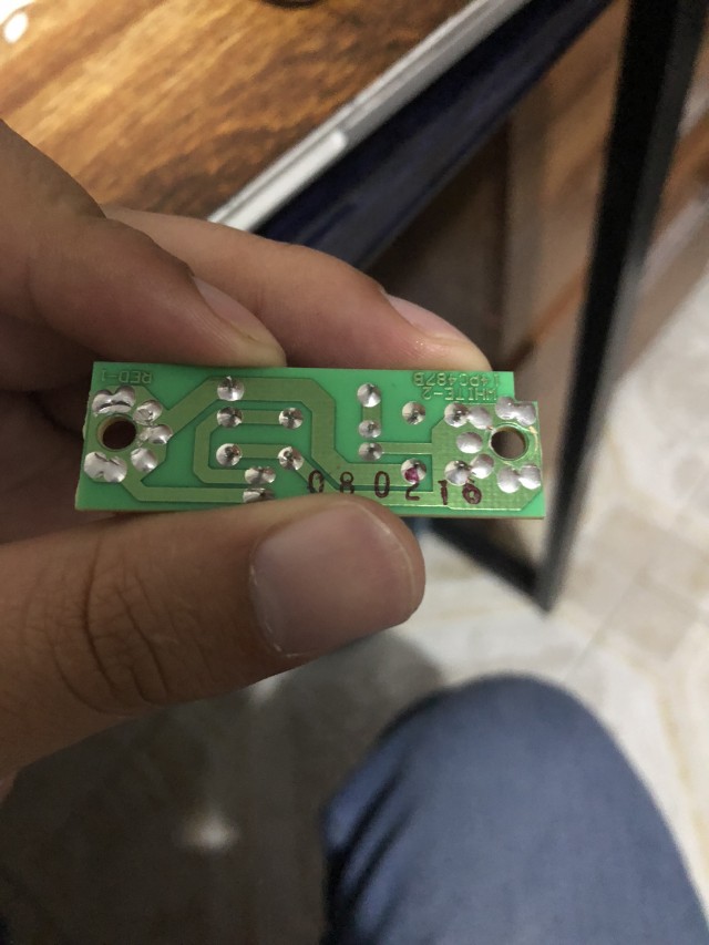
What i'm trying to do is to replicate the function of the button in my garage to open the door, i dont want to use the rfid part, i have this circuit, that, for what i understand it is just a simple cuircuit that gets closed when the switch is pressed.
What i don't understand is what the capacitor and resistor is for? and how everything (the paths and the components) work?
If someone can help me to understand this and to guide me so i can replicate this in a protoboard, so i can just send a digital signal to a port in my arduino and activate the circuit, i will be so thankful.
currently i have the arduino program working, event the app, what i dont get is how to activate the cuircuit, i have heard that i need a relay, i am currently investigating about that, but i want to know more about the circuit job.

regards,
I have in my house an automatic front door for my car, this has a remote control. I'm trying to use an arduino mega and ethernet shield to create a service to open my door using an Apple Watch App.
I am a programmer, i don't have too much experience with cuircuits and electronics, i barely know how some components work.
What i'm trying to do is to replicate the function of the button in my garage to open the door, i dont want to use the rfid part, i have this circuit, that, for what i understand it is just a simple cuircuit that gets closed when the switch is pressed.
What i don't understand is what the capacitor and resistor is for? and how everything (the paths and the components) work?
If someone can help me to understand this and to guide me so i can replicate this in a protoboard, so i can just send a digital signal to a port in my arduino and activate the circuit, i will be so thankful.
currently i have the arduino program working, event the app, what i dont get is how to activate the cuircuit, i have heard that i need a relay, i am currently investigating about that, but i want to know more about the circuit job.
regards,