Hi,
I`m following Ben Eaters videos to make an 8bit CPU/Computer..
https://eater.net/bbcpu8-registers/
(look at video part 5)
I have not got far..:
The clock was first and thats working fine.
The registers are next - and thats the problem.
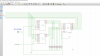
I can get the register to read data from the bus - tested by grounding some pins out here and there.
No matter what I try, I cannot get it to send data back to the bus.
I am VERY sure I have built it correctly, as I checked his schematic, board layout, and checked the datasheets for the IC`s.
The data is read fine into the 74LS173 -which has its output turned on, so that I can see the data on LED`s.
So that works fine.
But when I try to send the data back to the Bus, nothing happens.
I am not an expert, but I do understand logic like this - hence I`m stuck - as logically - is should work!
I have tried changing the 74LS245 (that releases the data to the bus, when `enable` goes low)
Also, I built two - both the same problem.
Its been rebuilt about 4 times now from scratch - still no luck
I guess its simple - but I cant see the problem!
Please help.
Thanks
I`m following Ben Eaters videos to make an 8bit CPU/Computer..
https://eater.net/bbcpu8-registers/
(look at video part 5)
I have not got far..:
The clock was first and thats working fine.
The registers are next - and thats the problem.
I can get the register to read data from the bus - tested by grounding some pins out here and there.
No matter what I try, I cannot get it to send data back to the bus.
I am VERY sure I have built it correctly, as I checked his schematic, board layout, and checked the datasheets for the IC`s.
The data is read fine into the 74LS173 -which has its output turned on, so that I can see the data on LED`s.
So that works fine.
But when I try to send the data back to the Bus, nothing happens.
I am not an expert, but I do understand logic like this - hence I`m stuck - as logically - is should work!
I have tried changing the 74LS245 (that releases the data to the bus, when `enable` goes low)
Also, I built two - both the same problem.
Its been rebuilt about 4 times now from scratch - still no luck
I guess its simple - but I cant see the problem!
Please help.
Thanks