electronicsLearner77
- Jul 2, 2015
- 306
- Joined
- Jul 2, 2015
- Messages
- 306
I am trying to run motor using the ST board B-G431B-ESC1 and the schematics are available in the link provided(I could not attach schematic as it is big). But i have several doubts,
a. There is OUT1 signal on page5, my understanding is it will be between 0 and V+, 0 when Low MOSFET is ON and V+ when the upper MOSFET is ON. Is it correct?
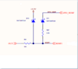
But this circuit

cannot measure battery voltages above 3.3V in that case D10 will be Forward biased and the BEMF1 signal will always be 3.3V. Please advise.
a. There is OUT1 signal on page5, my understanding is it will be between 0 and V+, 0 when Low MOSFET is ON and V+ when the upper MOSFET is ON. Is it correct?
But this circuit

cannot measure battery voltages above 3.3V in that case D10 will be Forward biased and the BEMF1 signal will always be 3.3V. Please advise.

