Kind Sires . . . . .
OBSERVATION . . . . . Anti Creep Slots
Note the sets of cutouts in the PCB stock between the 2nd and 3rd set of contacts above.
Those are anti creep slots.
By their width and spacing . . . I see your unit as probably being a 120VAC powered unit. . . .right ?
There seems to be marginal / borderline spacing between adjacent power traces . . .thus the cut outs.
Without them the solid board between those points would be subject to time developed deposition of airborne :
lint, fabric fuzz, dust, human and pet dander, crawling insect "leftovers" , smog / dirty air /with its/ carbon deposits and the conditions being exacerbated by overall high air humidity.
Eventually, a mat of this collected deteris could develop between voltage potential points and have a flash over to occur..
Now I assume . . . .AR57 . . . . . that you found that disconnect workaround worked for you and now have that unit all back together and are forgetting it.
Your fix . . . . being akin to . . . . . OH MY, my 2nd car has a flat, so you pull out its spare tire and put it on and then garage that one car, since you use it only " every 5-10 years".
You say . . . . .
I suspect this "special component" they devised is not very reliable. I assume this as i can not find a manufacturer datasheet of it AND the many "complaints" of its quality (e.g. https://www-elektroda-pl.translate....auto&_x_tr_tl=en&_x_tr_hl=en-GB&_x_tr_pto=nui) so i disabled this feature.
Au contraire . . . . .I say
that component is working absolutely fine .
You know the relays coil is good , because it is engaging the Safe Sense circuitry and stopping the shred motor, and when you took one? two? terminal(s) loose, the coil released the armature and the two contact sets opened.
Blame needs to be directed to the discrete components array that constitute the Safe Sense circuitry and that is starting with Q3 and then passes up to Q4 discrete transistor circuitry and a fault condition is sent over to the left to Q2 transistor where it shuts down base drive to Q1, which is being activated to drive the other .. . ..more recognizable relay . . . . . that is used for engaging the shred motor power.
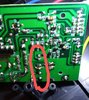
COMMENT . . . .
on the pair of yellow ceramic HV Y type capacitors associated with the center relay contacts.
Inspecting the top relay contact terminal , I am seeing its foil trace slant down and connect int both bottom leads of the paired capacitors . . .and ALSO catching one lead of a 2.2 meg res which as its other lead going down to connect to another series arranged 2.2 meg res that connects to a large yellow wire . My base suspicion is that this wire is going to connect to the pretty chromed and slotted escutcheon . . . . electrically floating panel . . . . which surrounds the paper slot input.
Now, the top relay contact has its foil going to the right and connecting to both of the top leads of that pair of yellow Y caps . . . . and then that paired connections foil path goes to . . . . .NO WHERE.
( I highly / absolutely suspicion an internal connection, made inside of the relay, of a resistor from there to one of the TOP set of relay contacts. )
You say . . . . .
The slot is not big enough for normal finger.
They are doing more than worrying about your fingers getting into that slot, they are preemptively shutting down motor power, the instant that a finger EVEN initially TOUCHES that plate !
HOW-DO-DEY-DO-DAT ?
The old water and saline enriched human body is being a walking antenna / receptor for the picking up of electromagnetically and electrostatically radiation from AC line wiring.
I'm having to jump ahead . . . . .WITHOUT someones eyes, further examining that circuit board and feed back to me.
BUT that feeble AC signal from the touching of the escutcheon ends up at the base of Q3 to be amplified and then sent up to Q4 for more of same, and then rectified to get a resultant DC signal that ends up at the base of Q2.
Now Q1 is the driver transistor which activates the motor run relay, if the unit had paper inserted and ws running.
The instant that Q2 activates, it places its C-E " short " across Q1 base and motor drive stops, until the body touch of the escutcheon is removed. ( assuredly . . . with some time induced mini delays introduced by circuitry inserted E-capacitors charge/discharge threshold timing)
Then, when you no touchee-touchee escutcheon . . . . . . the loss of that amplified 60~ hum and its turn off of Q2, lets the shredder motor run again.
Thaaaaaaaaaaaasssssssit . . . . . . . . UNTIL such time that a person to feedback requested info from that board . . . feeds back info . . . . for me to make a FULL, in depth analysis.
Be it
AR47, doing yeoman duty . . . . . or that sole
Polski, that is wanting to get
HIS unit BACK to
NORMAL.
73's de Edd . . . . .
I never had / used one, but, I perceive that a new fangled work cubicle, is just being a padded cell without a door.
.
 Enter to Win a Raspberry Pi 4 built into a compact keyboard! We'll be selecting the winner at the end of this month - click here for more information.
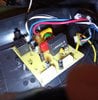
") )
)