Maker Pro
Maker Pro

Creative T3200 speakers help

Uros MIlosevic

Sep 14, 2016
15
Joined
Sep 14, 2016
Messages
15
Hello guys,
I got 2.1 creative speakers and when i plug them in wall and turn switch on nothing happens, power led wont blink, no sound, nothing.
Things i already checked:
1) Transformer(220V-12V)-With multimeter, working.
2) Fuse-with multimeter, working, no damage.
3)Amp chip-with multimeter, have 17V in datasheet says its ok.
Do somebody have any clue what is the problem or what to check next?

Thank you and sorry for my bad english
 

73's de Edd

Aug 21, 2015
3,622
Joined
Aug 21, 2015
Messages
3,622
Sir Uros . . . . . . .

NmE3MjRkYjAzZDQ0N2ZmYjQ4YzQ0NjdjZTdhNjk5N2OOoRadN7Ww8jcRXk2rsJukaHR0cDovL21lZGlhLmFkc2ltZy5jb20vMTg2YThlMDg0MzI2Nzc5MDA2NzQ0NWZjMzBiZDFjZWE2MGQ1YWE4OGQ0YjY4ZWI5M2Y0ZmMxNDA3NWQxYTAxNS5qcGd8fHx8fHwzOTN4Mjk0fGh0dHA6Ly93d3cuYWR2ZXJ0cy5pZS9zdGF0aWMvaS93YXRlcm1hcmsucG5nfHx8.jpg


What is the main amplifiers chip number. And can we get some good closeup photos of the main board ?

73's de Edd
 
Last edited by a moderator:

73's de Edd

Aug 21, 2015
3,622
Joined
Aug 21, 2015
Messages
3,622
Sir Uros MIlosevic . . . . . . .

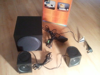
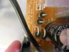
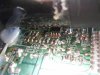
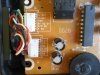
GREAT photos . . . to see exactly what ? we have there . . . . but may need upgrade of the last two on their closeness and lighting . . . . if being required.

O K lets get started on the first aspect of what might be at fault .
You have done great on your initial analysis and its findings.
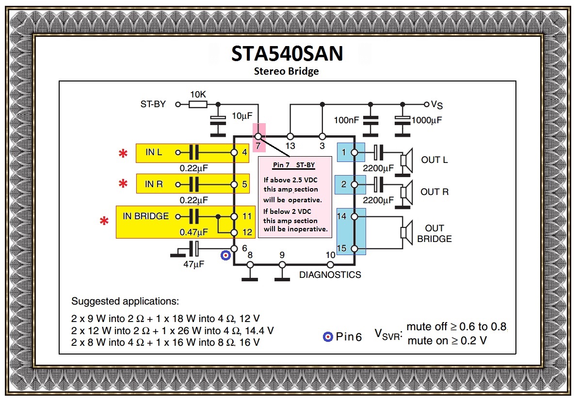
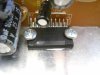
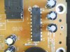
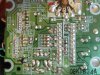
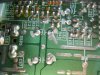
Now lets look at the main noisemaker for the unit . . .that STA540 unit.

Initially look at pin 6 and see if there is only a 47 ufd electrolytic connected there, as this pin also has the capabilities of muting the units sound . . . IF . . . being used.
If nothing else is connected to pin 6, then move on to use the connected speakers and powering up the unit to see if there is voltage at that pin 7 in accordance to my PINK note.

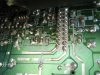
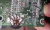
? ? ? Are the heavy RED and BLACK wire pair going to the units WOOFER ???

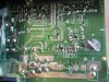
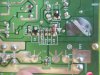
If there is less than 2VDC at pin 7, we have a problem of that level of activation voltage NOT coming in from a lower level audio portion of the set elsewhere.

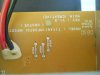
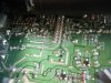
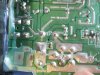
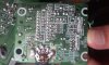
( The white connector with multi ? 6 ? leads on your very last photo. )

If there is >2.5 VDC there . . . I will then show you how to check out this section with but a mere clip jumper lead and an 0.01 ufd isolation / coupling capacitor.


Standing by for your findings. . . . . .


TECHNO REFERENCING:

chCEelV.jpg


73's de Edd

et al . . . . .

Сјајних фотографија. . . да видимо тачно шта? имамо ту. . . . али ће можда морати помак у последње две о њиховој блискости
и осветљење. . . . ако се тражи.

О К Започнимо на првом аспекту онога што може бити крив.
Сте урадили одличан на својој почетној анализи и својим налазима.
Сада омогућава поглед на главном Ноисемакер за јединицу. . .да СТА540 јединицу.
У почетку погледати на пин 6 и види да постоји само 47 УФД еллецтролитиц тамо повезани, јер овај пин такође има могућности мутинг
јединице звук. . . АКО . . . се користи.
Ако ништа друго повезан са пин 6, а затим пређите на коришћење цоннецтиед звучнике и напајање до јединицу да видите да ли је напон у том пин
7 у складу са мојим ПИНК белешке.

? ? ? Да ли су тешка црвена и црна жица пар иде у јединицама воофер ???

Ако има мање од 2Вдц на пин 7, имамо проблем тог нивоа активирање напона не долази из нижег аудио ниво део постављен на другом месту.
(Бела конектор са мулти? 6? Води на последњој фотографији.)
Ако постоји> 2.5 ВДЦ тамо. . . Ја ћу вам онда показати како да проверите овај део са пуки клип јумпер олово и један 0.01 УФД изолација / спојнице
кондензатор.


Чекамо својим открићима. . . . . .


Тецхно референцирање:

OOOOOO

Sjajnih fotografija. . . da vidimo tačno šta? imamo tu. . . . ali će možda morati pomak u poslednje dve o njihovoj bliskosti
i osvetljenje. . . . ako se traži.

O K Započnimo na prvom aspektu onoga što može biti kriv.
Ste uradili odličan na svojoj početnoj analizi i svojim nalazima.
Sada omogućava pogled na glavnom Noisemaker za jedinicu. . .da STA540 jedinicu.
U početku pogledati na pin 6 i vidi da postoji samo 47 UFD ellectrolitic tamo povezani, jer ovaj pin takođe ima mogućnosti muting
jedinice zvuk. . . AKO . . . se koristi.
Ako ništa drugo povezan sa pin 6, a zatim pređite na korišćenje connectied zvučnike i napajanje do jedinicu da vidite da li je napon u tom pin
7 u skladu sa mojim PINK beleške.

? ? ? Da li su teška crvena i crna žica par ide u jedinicama voofer ???

Ako ima manje od 2Vdc na pin 7, imamo problem tog nivoa aktiviranje napona ne dolazi iz nižeg audio nivo deo postavljen na drugom mestu.
(Bela konektor sa multi? 6? Vodi na poslednjoj fotografiji.)
Ako postoji> 2.5 VDC tamo. . . Ja ću vam onda pokazati kako da proverite ovaj deo sa puki klip jumper olovo i jedan 0.01 UFD izolacija / spojnice
kondenzator.


Čekamo svojim otkrićima. . . .


Edd
 
Last edited by a moderator:

Uros MIlosevic

Sep 14, 2016
15
Joined
Sep 14, 2016
Messages
15
Thanks you for your time.
I will go and take some good pics tomorrow and check these pins. Yes, red and black wires are from woofer and white connector is from 12V power supply
 

Uros MIlosevic

Sep 14, 2016
15
Joined
Sep 14, 2016
Messages
15
Here are better pics (same pic are from same board but different angle and some is from "remote" board)
 

Attachments

  • DSCN2938.JPG
    DSCN2938.JPG
    155.9 KB · Views: 166
  • DSCN2939.JPG
    DSCN2939.JPG
    147.1 KB · Views: 135
  • DSCN2940.JPG
    DSCN2940.JPG
    212 KB · Views: 176
  • DSCN2941.JPG
    DSCN2941.JPG
    319.8 KB · Views: 107
  • DSCN2942.JPG
    DSCN2942.JPG
    241.9 KB · Views: 142
  • DSCN2943.JPG
    DSCN2943.JPG
    219.9 KB · Views: 175
  • DSCN2944.JPG
    DSCN2944.JPG
    225.6 KB · Views: 142
  • DSCN2945.JPG
    DSCN2945.JPG
    241.2 KB · Views: 135
  • DSCN2946.JPG
    DSCN2946.JPG
    151.1 KB · Views: 101
  • DSCN2947.JPG
    DSCN2947.JPG
    197.9 KB · Views: 162
  • DSCN2948.JPG
    DSCN2948.JPG
    223.1 KB · Views: 196
  • DSCN2949.JPG
    DSCN2949.JPG
    289.6 KB · Views: 129
  • DSCN2950.JPG
    DSCN2950.JPG
    240.6 KB · Views: 148
  • DSCN2951.JPG
    DSCN2951.JPG
    249.7 KB · Views: 139
  • DSCN2952.JPG
    DSCN2952.JPG
    257.9 KB · Views: 141

Uros MIlosevic

Sep 14, 2016
15
Joined
Sep 14, 2016
Messages
15
I checked pin 6 and pin 7, 6 gives 1,3V(that is okay i guess) and pin 7 gives 1,5(that is not okay?).
What next?
 

73's de Edd

Aug 21, 2015
3,622
Joined
Aug 21, 2015
Messages
3,622
Sir Uros MIlosevic. . . . . . .

I just consulted that units operational manual as its quick start set up, which gives little more than labelling of connections and is being shared in 8 languages.
When I saw your last pictures, there was the separate 20 pin IC which I then researched out as being just another dual 5 watt amplifier. The main HEAVIER IC should suffice for a bass woofer driver in bridged drive mode and your smaller right and left speaker are driven by the other two sections of that amp..
Also, by using your last submitted smaller boards electronics pics, they showed a switch mounted onto a very small rotary volume control . . . . . .much like you would find being used on a small transistor pocket radio.

I was then thinking that the 20 pin unit / amp just might then be exclusively serving as a headphone drive circuit but I see NO connector for a headphone to be plugged into.
The thought was then being . . . that the headphone was turned on with that switch . . . and its volume control was then serving to adjust the headphone audio level..

OR, more importantly, if that switch was turned OFF, then there was a S-BY voltage being directed to the main amplifier, to make it operational ..
BUT it looks like this situation was not being the case.
I do see a separate BASS volume control for the woofer on its housing and the small volume control and its attached switch, which must serve for the WHOLE systems power switch and right and left speakers volume.
That control and its switch seems to be mounted on the docking station for a MP3 player as is being seen in your last pictured electronics.

Now from your last voltage readings from, and your having found found ONLY a capacitor connected to pin 6, all seems to be correct on that pin 6 voltage connection.

BUT with the LOW voltage now being found on pin 7, THAT low level, seems to signify why the system is now muted.
In looking at the parts on the second board that you showed, in the cut out shown below, I immediately would want to know the DC voltage being found across the YELLOW circled DZ1 zener diode, with power applied and the unit turned on.
Its BLUE band end would be its positive voltage end.
Standing by for your feed back

POWER SUPPLY AREA:

U3200 zener diode..png


73's de Edd
 
Last edited by a moderator:

Uros MIlosevic

Sep 14, 2016
15
Joined
Sep 14, 2016
Messages
15
Okay, thanks for answer, i will post results of diode later.
I was searching for error i think i have clue why is not powering out. First, there are two amp chips one for woofer and one for satellites, amp chip for satellites dont have any voltage, i know its because small board dont get any power from main board. So, error is on main board because power cant get in smaller board and switch to turn system on. Now i only need to see what preventing power to get up there and fix that.
 

Uros MIlosevic

Sep 14, 2016
15
Joined
Sep 14, 2016
Messages
15
Sorry, i was on work trip and couldn't work on this, i measure the voltage on zener diode, its about 12V
 

73's de Edd

Aug 21, 2015
3,622
Joined
Aug 21, 2015
Messages
3,622
Sir Uros MIlosevic . . . . . . .

The anode of that zener is connected to ground.

With no power applied take ohmmeter and ohm from that ground connection to the right bottom corner of Q1 above it
and then to ohm the bottom right corner of Q5. If they are not being grounded or of a low resistance then lets try a power up and measure the voltages.

Turn on the unit with its switch and have AC plugged in.
Keep DC voltmeter negative lead to that same ground and then test DC voltage level present on the :

Bottom left terminal of Q5
Top center terminal of Q5
Bottom right terminal of Q5
Log down Q5's voltages to pass to us.

Then move on up to Q1
Bottom left terminal of Q1
Top center terminal of Q1
Bottom right terminal of Q1
Log down Q1's voltages to pass to us.

Confirm if Q5 is marked as ALC or ALG
I can not make out Q5's mark at all unless it is (A?) SG

That is all . . .


73's de Edd
 
Last edited by a moderator:

Uros MIlosevic

Sep 14, 2016
15
Joined
Sep 14, 2016
Messages
15
Q1 is ALG. Q5 is ASG.
Measurements:
Q1 gives 18,32kOhms, Q5 over 200kOhms.

Bottom left terminal of Q5 -12,7V
Top center terminal of Q5 - 12,7V
Bottom right terminal of Q5 - 17,8V

Bottom left terminal of Q1 - 12,7V
Top center terminal of Q1 - 12,7V
Bottom right terminal of Q1 gives no voltage at all.
 

73's de Edd

Aug 21, 2015
3,622
Joined
Aug 21, 2015
Messages
3,622
Q1 is ALG. Q5 is ASG.

Measurements:
Q1 gives 18,32kOhms, Q5 over 200kOhms.

That is telling us that we have no heavily loaded down or shorted
secondary supply lines.

Bottom left terminal of Q5 -12,7V
Top center terminal of Q5 - 12,7V
Bottom right terminal of Q5 - 17,8V

Looks O.K.

Bottom left terminal of Q1 - 12,7V
Top center terminal of Q1 - 12,7V
Bottom right terminal of Q1 gives no voltage at all.

Let's assign those terminals now

Bottom left terminal of Q1 . . . Base . . . . . . . - 12,7V
Top center terminal of Q1 . . . .Collector . . . - 12,7V
Bottom right terminal of Q1 . .Emitter . . . . . . . gives no voltage at all.

Could we be so lucky as to just have a Q1 that has
internally popped
its emitter beam lead ?


Re Test again, but have the rotary volume knob be rotated full CCW so as to
turn off its power switch.
Plug the unit in to power and then retest the 3 terminals of the Q1 and Q5
transistors to see what the change in voltages are then.


73's de Edd
 
Last edited by a moderator:

Uros MIlosevic

Sep 14, 2016
15
Joined
Sep 14, 2016
Messages
15
Okay, i tested again, with whole system switched off and on min volume.
Results are identical. Is it possible that Q1 is making problem?
 

73's de Edd

Aug 21, 2015
3,622
Joined
Aug 21, 2015
Messages
3,622
Sir Uros MIlosevic . . . . . .


I certainly hope so.
Since your last testing revealed no dead shorts on the SUB power supply lines.

This time, advance the volume knob up to your usual listening level, and now, lets go back to metering.

Use the DVM in its DC current monitoring function which would typically involve setting it to its 1 ampere DC range and usually a moving of the input connector of the + RED test lead input to a 1 AMP connector.
The NEGATIVE test lead stays plugged in as it was.

That gets you prepared to measure up to 1 ampere of current passage between the meters RED and BLACK test leads.
( Probe polarity is irrelevant at this particular time.)
Apply AC power to the unit now, and hopefully, be ready to hear music ?

You then go to the Q1 transistor and place one probe to its Collector and the other probe to its Emitter for just an instant..
Was there then any audio activity or a speaker pop ?
If there is activity, get an audio stream coming from the speakers.
The meter reading should then give us the guesstimated required current level to then select an appropriate powered replacement for Q1 in a common leaded transistor instead of its current surface mount..

Hoping that transistor was the problem !

73's de Edd
 
Last edited by a moderator:

Uros MIlosevic

Sep 14, 2016
15
Joined
Sep 14, 2016
Messages
15
Okay, when i do all thing you sad, green LED goes on but i do not hear any sound. Same thing when something is playing. When i let multi-meter pipes LED goes off and that is it.
So there is a chance that Q1 is making a problem? What next?
 

73's de Edd

Aug 21, 2015
3,622
Joined
Aug 21, 2015
Messages
3,622
.


Sir Uros MIlosevic . . . . .


When i let multi-meter pipes LED goes off and that is it.
I interpret that "pipes" statement as:
When you remove either of the meter probes, the power LED goes off, and the unit is still inoperative.

So there is a chance that Q1 is making a problem?
That now tells us that Q1 transistor has a blown emitter.

The reason for doing the current consumption metering was to ascertain the power level of a transistor needed to replace that unit, go back and give us the milliamperes of current that was passing through your meter.
If it is being af a logical value, we will then just install a temporary jumper wire from Q1's C-Emitter and power up or power down the unit while we analyze what else is at fault in one of its subordinate power supplies or connections.

We then just power up long enough to take measurements.

Did you have both the units frontal bass volume knob turned up as well as the smaller thumbwheel volume knob turned up?.

What next?
Your photo #11 of your 11/15 photos is related to the smaller separate circuit board that has the units low level audio and your right and left channels amplifier on it.
If you note connector J2 it has a +12 VDC connection in the center of it.
In a NO POWER condition can you ohm from that pin to the emitter of Q1 and see if there is being a direct connection between them .

73's de Edd
 

Uros MIlosevic

Sep 14, 2016
15
Joined
Sep 14, 2016
Messages
15
Hello,
Both knobs were turn on half-way.
Multimeter cant measure any current, its show 000 in every test.
Yes, J2 +12VDC has directly connected to bottom right leg of Q1.

What next?
 

73's de Edd

Aug 21, 2015
3,622
Joined
Aug 21, 2015
Messages
3,622
Multimeter cant measure any current, its show 000 in every test.

Give me the meters brand and model so that I can see if you possibly had it set wrong . . .but we DO know that you did have it in a current function, possibly AC, since it passed the power supply voltage through the probes. That wouldn't have happened in a voltage function setting .

You gave me very good pictures of the foil sides of the 2 boards.
But I don't see the component side of the smaller board.

We now know that the J2 +12 V connection is receiving the Q1 switched voltage into that board from the main power supply board..
We now need to confirm that J2 + 12 on the small board is now getting power distributed to all points on it.

But first I still need to find out the current being passed by Q1 so that we can get power through that transistor to then free your meter for voltage measurements on the small board.
Do you have any loose small NPN transistors . . .or ones that you can take from some of your "scrap" electronics, to see if one of them will meet out power needs for the replacement of Q1.
I need their numbers to research, AFTER we successfully read the current that is passing through Q1.

Also, none of the pictures gave me a good enough view of the one 8 pin IC on the large board to be able to identify it. I am going with an educated guess that it is probably a 4558 dual op amp.
Am I correct ?


73's de Edd


.
 

Uros MIlosevic

Sep 14, 2016
15
Joined
Sep 14, 2016
Messages
15
Multi meter is womax allqsun em390. I will look for some transistors around the house.


20161019_111933.jpg 20161019_111940.jpg 20161019_112007.jpg 20161019_111945.jpg 20161019_112025.jpg 20161019_111933.jpg 20161019_111940.jpg 20161019_111933.jpg 20161019_111933.jpg 20161019_111940.jpg 20161019_112007.jpg 20161019_111945.jpg 20161019_112025.jpg
 

Attachments

  • 20161019_112007.jpg
    20161019_112007.jpg
    241.2 KB · Views: 177
  • 20161019_112025.jpg
    20161019_112025.jpg
    250.6 KB · Views: 140
Top