flippineck
- Sep 8, 2013
- 358
- Joined
- Sep 8, 2013
- Messages
- 358
I have a small through-hole type current transformer
https://docs.rs-online.com/93d6/0900766b8169af7d.pdf
with a coil ratio of 2500:1 with a single pass of live 240V AC 6mm² conductor through the hole.
If my calculations are correct, feeding the secondary across a 100Ω burden resistor should result in a voltage output swing up to around +-2.4V, proportional to the primary current ranging from 0 - approx 40A.
The plan is to then apply a suitable DC offset using two 330kΩ resistors as a reference divider, to give a 0-5V input suitable for an arduino analog input pin.
https://learn.openenergymonitor.org/electricity-monitoring/ct-sensors/interface-with-arduino
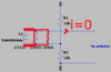
If left with the primary powered & with the secondary open circuit (e.g. if the 100Ω resistor fails open circuit), it could result in a high voltage resulting across the secondary, maybe up to the primary voltage x the coils ratio - 600kV?
Would it be a good or a bad idea to include in the circuit, a neon lamp in parallel with the burden resistor, would that work as a belt-and-braces way to mitigate against burden resistor failure?
I
https://docs.rs-online.com/93d6/0900766b8169af7d.pdf
with a coil ratio of 2500:1 with a single pass of live 240V AC 6mm² conductor through the hole.
If my calculations are correct, feeding the secondary across a 100Ω burden resistor should result in a voltage output swing up to around +-2.4V, proportional to the primary current ranging from 0 - approx 40A.
The plan is to then apply a suitable DC offset using two 330kΩ resistors as a reference divider, to give a 0-5V input suitable for an arduino analog input pin.
https://learn.openenergymonitor.org/electricity-monitoring/ct-sensors/interface-with-arduino
If left with the primary powered & with the secondary open circuit (e.g. if the 100Ω resistor fails open circuit), it could result in a high voltage resulting across the secondary, maybe up to the primary voltage x the coils ratio - 600kV?
Would it be a good or a bad idea to include in the circuit, a neon lamp in parallel with the burden resistor, would that work as a belt-and-braces way to mitigate against burden resistor failure?
I


")