Maker Pro
Maker Pro

DC Bus in a Loop Configuration. Problem?

LKO Railroad

Aug 9, 2013
43
Joined
Aug 9, 2013
Messages
43
I am building a model railroad. The track requires a constant 15V DC on the rails. A radio receiver module within the locomotive receives commands from a handheld controller. The module then regulates the 15V DC to the motor to control locomotive speed and direction. A typical locomotive draws 250-500 mA. There likely will never be more than 8-10 locomotives in operation simultaneously across the entire layout.

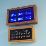
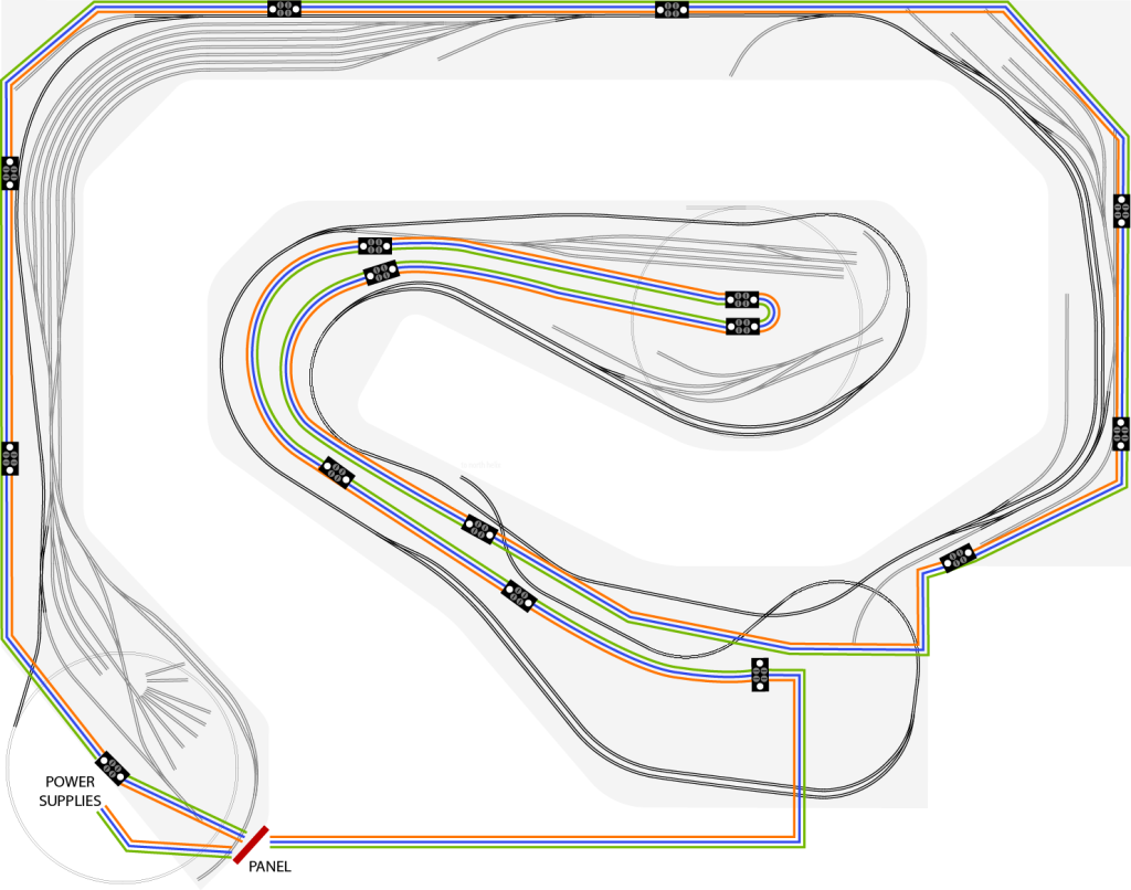
I am using a Mean Well 15V 7A switching power supply to power the rails. The power supply is connected to an ammeter about 6 feet away. From the ammeter a loop of bus wire (orange) goes all the way around the layout. All wire is 12AWG solid THHN. The overall length of the bus around the layout is approximately 140 feet. A full description is here.

There are two addition power supplies and buses in the same fashion. One for controls (blue), the other for accessories (green). Essentially there are 3 copies of the power bus on the layout.

I have been informed that running the bus in a loop may be a problem. None of the gang I hang with knows anything more about electricity than I so I come hat in hand to you guys.

Will my DC bus loops be a problem? Thank you in advance.

power_bus_routing-1024x806.png
 

Arouse1973

Adam
Dec 18, 2013
5,178
Joined
Dec 18, 2013
Messages
5,178
Hello LKO
The only thing that might be an issue is the resistance of the wire causing a voltage drop that effects the train the furthest away from the power supply. The fix for this would be to increase the size of the wire. The black blocks are connectors right? Can you just explain a bit about how the wires terminate in the panel, what's the red rectangle in the picture?
Adam
 

Arouse1973

Adam
Dec 18, 2013
5,178
Joined
Dec 18, 2013
Messages
5,178
Worked out this I think it's right, you will have to decide if it will be a problem. This is might be worst case and an example. 140 ft of 12 AWG will have 0.2 Ohms resistance. Ten trains requiring 500 mA will need 5 Amp which will drop 1 Volt of the power supply to this position. This will obviously be lower closer to the power supply because of the reduced resistance. I don't know if all trains could end up at the end all together?
Adam
 

LKO Railroad

Aug 9, 2013
43
Joined
Aug 9, 2013
Messages
43
The black blocks are connectors right?

Correct. They are terminal blocks where the rails connect to the bus.
100_6527a-150x150.jpg


what's the red rectangle in the picture?

The red rectangle is the ammeter panel. At the ammeters is where the bus loop joins together.
100_6499a-150x150.jpg


Ten trains requiring 500 mA will need 5 Amp which will drop 1 Volt of the power supply to this position.

A 1V drop is satisfactory. The running speed difference of the locomotive between 14V and 15V is barely detectable. Certainly good enough. I attached an automotive halogen headlight to the terminal block furthest from the ammeter panel. The headlight measured 4.6A. The voltage at the headlight was 14.2V.

Is there any reason I cannot keep the loop? It provides two paths for a load anywhere on the layout, correct? Is dual paths an issue for some reason? The other train guys seem to think it is although they can't explain why. They speak of possible "ringing"?
 
Last edited:

Arouse1973

Adam
Dec 18, 2013
5,178
Joined
Dec 18, 2013
Messages
5,178
Having the power cables as a loop may cause it to pickup more noise from the trains as they operate. But this is a unlikely to be too much of an issue. Yes you could get over shoot depending on how well damped the system is, as for ringing this is when part of the system oscillates at its tuned frequency when excited by a step response of current. Considering the small inductance and relatively large capacitance of the circuit I doubt ringing will be much of an issue. If you do get significant overshoot then a small RC snubber connected across the terminal block should sort this out. I'll see if I can work something out.
Adam
 

Arouse1973

Adam
Dec 18, 2013
5,178
Joined
Dec 18, 2013
Messages
5,178
Right here is the formula I used to roughly calculate your system.

INDUCT WIRE.PNG
The first circuit I used shows ringing without a load.
INDUCT1.JPG
This is with a 10us rise-time which is quite fast, I think you will have more delay in your circuit than this. This doesn't include any capacitance the rest of the system has, adding this will stretch out the overshoot and reduce the amplitude slightly. But the root cause of this overshoot is the rate of change of the current in the system and lack of low damping. So you have two options, increase the rise time which I think your system will naturally do, or add some damping which I also think your system will do.
10u.jpg
This again but with 100us rise-time, almost gone.
100u.jpg
And this one with a 10R load.
10R..jpg
Adam
 

LKO Railroad

Aug 9, 2013
43
Joined
Aug 9, 2013
Messages
43
Please forgive my ignorance. What determines the rise time? If I can assume it means how quickly and heavily the circuit is loaded then that is beyond my control, is it not? Start up of the motor inside any given locomotive would determine that, correct? Or do I completely misunderstand?

Can you explain to me in layman terms what a 10R load is? Does that mean 10 ohms and thus a 1.5A pre-load on the bus?

The damping you refer to is the RC snubber at the terminal blocks, correct? I am not familiar with the math to calculate the values. Can you supply or direct me to a resource to calculate please?
 

Arouse1973

Adam
Dec 18, 2013
5,178
Joined
Dec 18, 2013
Messages
5,178
You got it. The load I used was an example or how to reduce the overshoot. It is likely there will always be a load from the trains. But you could add a load if you needed to, 10R might be too low but I just used this to show the idea. Yes you cant control the risetime but as I said I doubt it will rise faster than 100us so the problem will not occur. I dont think you will need the snubber because I dont think the overshoot is not going to be an issue.
Adam
 

LKO Railroad

Aug 9, 2013
43
Joined
Aug 9, 2013
Messages
43
Most excellent. Thank you for the follow up. For a margin of safety I think I will add a 1A load at the furthest point in the loop. Thanks again for all your help.
 

Arouse1973

Adam
Dec 18, 2013
5,178
Joined
Dec 18, 2013
Messages
5,178
No probs, you will have to let us know how it goes.
Cheers
Adam
 

KrisBlueNZ

Sadly passed away in 2015
Nov 28, 2011
8,393
Joined
Nov 28, 2011
Messages
8,393
I can't foresee any problem with running the power rails in a loop like that.

You might want to put a low ESR electrolytic across each power supply rail at each connector - that will reduce interference emission from your wiring, since the rapidly changing currents will be kept to the local loop between the track and the power outlet box. Something like http://www.digikey.com/product-detail/en/EGPA250ELL222MK30S/565-3377-ND/3528510 (2200 µF) would be suitable.

But then again, with all that distributed capacitance, the power supply might not be able to start up! You would get some benefit (in terms of reduced interference) from a smaller ceramic capacitor across each connector - something like http://www.digikey.com/product-detail/en/FK24X7R1E225K/445-8514-ND/2815444 (2.2 µF)
 

LKO Railroad

Aug 9, 2013
43
Joined
Aug 9, 2013
Messages
43
The two capacitors remind me of my standard decoupling arrangement for ICs other than the values. I typically use a 47uF and .01uF. Unfortunately, I do not have a scope to see what's going on nor do I have sufficient understanding of electronics to make educated guesses. A friend, now deceased, long ago told me to place the two decoupling capacitors on any IC project I construct. I work blind trusting the example circuits in datasheets. :(

As I understand it, the large value capacitor removes low frequency noise/spikes while the small value capacitor removes high frequency noise/spikes. Is that basic understanding correct? If so, how concerning is it the rails and/or bus be free of this noise?
 

Arouse1973

Adam
Dec 18, 2013
5,178
Joined
Dec 18, 2013
Messages
5,178
Yes that's part of the story. The other part is although the capacitors will shunt noise from the power supply they also supply the necessary switching current demanded by the circuit. The smaller ceramic capacitors deal with the faster switching circuits demands and the larger capacitors deal with slower current demands. They help to stabilise the PDN (power distribution network).
Adam
 

LKO Railroad

Aug 9, 2013
43
Joined
Aug 9, 2013
Messages
43
As you see my power bus is already installed with the exception of the damping load discussed earlier which will be installed before operation. Should I also install the capacitors before operation? If the power supply won't start then I assume I would reduce the value of the large capacitors until the power supply will start reliably. Is some large capacitance better than no capacitance in this case?

On the track bus there are only motors (350mA max each) drawing current. The motors are controlled by the radio "module" in the locomotives. The module uses some sort of PWM to control motor speed. These modules are sold to the model railroad hobby as suitable to run on any DC powered track including one special type called Digital Command Control (DCC). Unlike my modules which receive commands via radio, the DCC systems use an AC square wave of varying pulse width on the tracks to send digital commands to each locomotive module. When I think of DCC relative to this capacitor discussion it seems to me the modules I have must not be sensitive to noise on the rails else they wouldn't work properly on a DCC track. Does that logic make sense?
 

Arouse1973

Adam
Dec 18, 2013
5,178
Joined
Dec 18, 2013
Messages
5,178
I would see how it runs without any modifications first. If you start to have issues like jittering trains or trains that won't run then we can look at implementing some of the solutions discussed.
Adam
 

KrisBlueNZ

Sadly passed away in 2015
Nov 28, 2011
8,393
Joined
Nov 28, 2011
Messages
8,393
The reason I suggested decoupling capacitors is mainly to keep noise contained locally. Without them, a lot more of the noise current will flow through the bus wiring and cause radiated interference. I would imagine there will be quite a lot of noise because of the movement of the wheels on the track, but maybe I'm wrong.
 

LKO Railroad

Aug 9, 2013
43
Joined
Aug 9, 2013
Messages
43
You are spot on about rolling wheels on track. Not exactly what you would call a secure connection. I imagine there is a lot of make/break going on.
 

KrisBlueNZ

Sadly passed away in 2015
Nov 28, 2011
8,393
Joined
Nov 28, 2011
Messages
8,393
Well, I would have thought so, but you don't see any sparks, which is why I was not sure.
 
Top