Maker Pro
Maker Pro

Dehumidifer - Does not Power On. Faulty Power Supply Board.

wills07417

Dec 26, 2014
18
Joined
Dec 26, 2014
Messages
18
Hello,

Unit: Rowenta Dehumidifier Model DH4010
Symptom: Does not power on. No standby led nor beeps. When working, the unit, once plugged into the wall, typically lights up the lcd display for about a second and makes a beep.

I'm a total beginner and would appreciate any kind advice on how to repair my dehumidifier. This is the first "project" which I've undertaken to actually try to learn more on electronics and avoid having to pay much more in costly service repair centers.

Luckily, I have two of these units. I've attached and checked the main control panel/led display circuit board from the problematic unit to the working unit and it's fine, which helped me isolate the problem to the power board. Unluckily there are no voltage markings anywhere on the board, which would guide me, nor have I found any service manuals or documentations online.

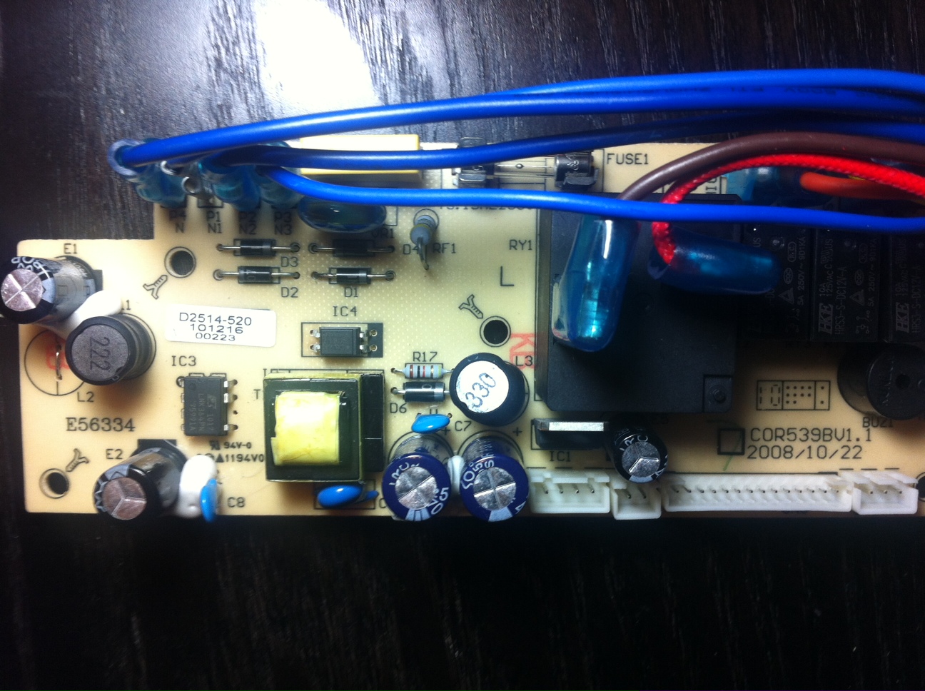
I've attached some pics of the board. DH4010PCB.JPG is the complete board view. The others are closer views of parts of the board.

Detail:
- AC (220v) power cord comes in at P1/N1. Power from the cord is also split and comes in via the brown wire into the big black box in the middle (sorry, I'm not sure what this is). The red wire out of that box appears to go down into a larger capacitor at the base of the unit which powers the dehumidifier compressor.
- Output to main control board via the 14 pin connector on bottom right
- When I first inspected the board, I noticed IC4 was cracked with some of the black covering chipped off. I replaced with the same (LNK364PN) power management chip, but no luck. Still no power.
- Fuse in the plug as well as on this power circuit board are good.
- I've visually inspected the 5 capacitors, and they seem to be clean, with no bulging/swelling at the top.
- No other signs of burns, melting, mess.

Would greatly appreciate a beginner's primer on how to troubleshoot this. As a complete beginner, would appreciate any step by step rudimentary instructions (ie. place multimeter red probe here...black probe here...set multimeter to xyz).

Thanks very much.
-Will

uc
 

Attachments

  • DH4010PCB.jpg
    DH4010PCB.jpg
    145.3 KB · Views: 410
  • DH4010PCB2.jpg
    DH4010PCB2.jpg
    144.8 KB · Views: 1,307
  • DH4010PCB3.jpg
    DH4010PCB3.jpg
    115.3 KB · Views: 702
Last edited:

Anon_LG

Jun 24, 2014
453
Joined
Jun 24, 2014
Messages
453
Welcome to electronicspoint!

You say in your post you are a complete beginner to electronics, you do however appear to know what you are looking for. If you are a beginner be very very very careful.

Has the appliance been in use for a while? If so the relays could have suffered mechanical wear damage. As the capacitors appear to be fine, the IC has already been replaced and the fuse checked this really only leaves the relays I would recommend you replace these. Should IC 3 have only 7 legs?

Are there any components on the reverse of the board? If so could you provide a picture.

I hope this helps you,
 

wills07417

Dec 26, 2014
18
Joined
Dec 26, 2014
Messages
18
Thanks for the warm welcome, Lavaguava!

Electronics and circuits have always amazed me, but i've never really had the time to dig into further, but i figure it's a good opportunity to pickup the hobby. I have a closet full of items that need fixing (next is an old vintage vox guitar amp, but i'll leave that till i'm a bit more experienced while i practice on the home appliances).

Yes, i'm quite aware of the dangers when working with open circuit boards. I've been shorting the capacitors with a wrench with rubber handles and using the hand in pocket technique...to be extra safe, i'm even using cloth gloves. the death warnings aren't very appetizing to me...

The dehumidifier actually hasn't been used for several months, and appears when trying to fire her up again on a damp/moist day here in HK, she never "woke up" from her hibernation. Completely dead, no leds, no sound, no hum from the transformer, nothing. There were no spectacular events that i could recall (ie. smoke, sparks, weird noises) when i last used it.

Actually, i had a typo in the original post, it was IC3 that "looked" bad, which i replaced, and yes, it is supposed to only have 7 legs.

I've attached a pic of the underside. Chip IC2 on the left is marked "ULN2003AG", small black component on the right is marked "PJ9D9 ER1". You can see the novice resoldering i performed for IC3.

Appears to be 4 "HKE" relays 10a 125vac and 1 "song chuan 855awp-1a-c2" 30a 240vac relay (the big one). No visible signs of anything peculiar. Any way i can test before going out and ordering replacements?

Also, for my understanding, is there a textbook way i can follow the "flow" of current and test each part of the circuit board by measuring the voltage through each component? Wouldn't a drop in voltage signal the possible culprit? or is this too simplistic? If so, would be great if you can advise how this can be done (where do i probe the red and black leads on my multimeter) and what to expect in regards to measurements.

Greatly appreciate all the help!

0B5TgBPdn_2NuS245SUJ2bm5PR00
 
Last edited:

Bluejets

Oct 5, 2014
6,922
Joined
Oct 5, 2014
Messages
6,922
The chip you have "replaced"....for want of a better word...... is a control chip for initial power to the board.
IC4 (above it to the right) is a feedback opto-isolator chip from the transformer (yellow Square device beside IC3) to IC4.

Shorting capacitors is a bad idea...instead, use a resistor...plenty of places to read about this on the web.
Similarly having one hand behind your back ( I hope this is an attempt at humor but many will take you literally)

If you are certain you are getting main supply in, then there is no longer a need (for you at least) to do any other live work so be absolutely certain everything is disconnected from high voltage.

Test the 4 diodes (D1,D2.D3,D4) these make up a bridge rectifier which supply IC3 and hence control to the transformer.
Again you can look up how to test these with supply disconnected and using any basic multimeter.
Check fuse with multimeter also. (not just visual) in circuit would be best as I have seen dicky connections there.

It is possible (probable) that the transformer has a fault which would explain IC3 blow up in which case a new board would be almost 100% required.
 
Last edited:

wills07417

Dec 26, 2014
18
Joined
Dec 26, 2014
Messages
18
Thanks very much, Bluejets.

Noted on the capacitor shorting. Will find myself a resistor or a lamp to connect it to in order to drain it.

I've checked the 4 diodes in circuit and get .5 v drop on all of them (placing along the right polarity). I've also checked the fuse (marked "Fuse 1" for continuity in circuit and it's fine. Are there any other fuses you can see on the board? Ie. i'm not sure what the "cylinders" marked "222" and "330" are.

If the transformer is at fault, would it be possible to just switch that out? Or is it that a bad transformer just wrecks havoc on the whole board?

Any further checks before resigning to ordering a new board? Any suggestion what the part number for this board is and where I can source it? I've googled some of the codes on it, but don't come up with anything.
 

HellasTechn

Apr 14, 2013
1,579
Joined
Apr 14, 2013
Messages
1,579
As the capacitors appear to be fine,
. Should IC 3 have only 7 legs?

1. Capacitors look ok.Keep in mind that i have encountered shorted capacitors that looked ok.
The only way to know for sure is to check with capacitometer. But 90% of the times if they look ok they are ok.

2. Yes ic3 can only have 7 pins because pin 6 is not used.
(Correct me if i am wrong) This chip is the one that feeds the high freq transformer and defines the output voltage by switching on and off.

If IC3 was damaged it would blow the fuse for sure and it would also damage the smoothing capacitors and the the rectifier bridge.

I agree with post #3. Only you do not need to discharge the caps because they have small capacitance and drain very fast.

You can check the voltage on the leads with a voltometer and just wait untill it gets low enough (below 20volts i would say). they sould drop down to zero very fast though.
 

HellasTechn

Apr 14, 2013
1,579
Joined
Apr 14, 2013
Messages
1,579
Test the 4 diodes (D1,D2.D3,D4)

It is possible (probable) that the transformer has a fault which would explain IC3 blow up in which case a new board would be almost 100% required.

Checking the diodes requires that you remove them from the PCB. My opinion is replace theb with a bridge rectifier just to be sure. (costs like 1$)

The transformer almost never fails. IC3 fail very often for a number of reasons.

My reccomendation.

Carefully plug the circuit into mains power and measure voltage across the pins of the Blue capacitors next to the transformer. If you get voltage there then you know that high voltage section si ok.

If not then replace ic3, replace the diodes with a bridge rectifier (easyer and faster) change E1,E2 caps and the fuse and you should be ok.

If you suspect a transformer failure then Google its code to find the diagram,remove it from the PCB and measure resistance among its terminals as shown on the diagram with a multimeter.
 

Bluejets

Oct 5, 2014
6,922
Joined
Oct 5, 2014
Messages
6,922
Tests I recommended were with power disconnected , hence check the diodes, I meant with diode test on a multimeter without power.
The reason I suggested you discharge the capacitors with a resistor is that one day, if you persist with bad habits, you will short out a large one and it may well blow up in your face.
The "cylinders" marked "222" and "330" appear to be chokes and should have near zero resistance.
The secondary of the transformer provides low voltage to the rest of your circuit so if faulty then nothing works so it cannot be "switched out" as you put it..
I doubt you will source the transformer as a part if this is the case which is why I suggested a replacement board if it proves to be at fault.
It is of course possible that you may have inadvertently damaged your new IC3 on installation with excessive heat but only further testing will determine this. It does contain some parts that could be damaged by static charge also.
This can come about by using soldering irons without any static protection.
Contrary to the suggestion above, transformers do fail and mostly on the primary side where windings are very fine gauge and flashovers between windings can occur causing open circuit.
If the electrolytics around the incoming section were faulty, it would lead to some instability but I doubt this is the case as they do look ok (no bulges in the tops and no leaking) you would still get some signs of life.
The 2 connections on the rear side of the board immediately above the surface resistor R31 should be your transformer primary and have a high resistance compared with the secondary which should be the 2 connections to the left of the yellow line on the painted white strip.
 

wills07417

Dec 26, 2014
18
Joined
Dec 26, 2014
Messages
18
Thanks everyone for the responses. Really appreciate folks taking the time on this.

So I checked voltage on the two blue caps by setting my multimeter on V (DC) with black probe on negative pin and red probe on positive pin (on the underside of the board where the caps are located). No voltage readings. Presuming I did this correctly, I should now go ahead and replace the 4 diodes (D1, D2, D3, D4) and the 2 other caps (E1 and E2). For my understanding and learning, why would no voltage reading on blue caps next to the transformer signal possible flaw on the diodes and E1/E2 caps?
Also, I tested the diodes in circuit as per Bluejets advice and got .5v drop on each...could this be a faulty reading because I did not take the diodes out of the circuit to test? It seems as though the readings correctly coincided with the direction of the polarity.

I've already replaced IC3 and checked the fuse is good for continuity, so that means I only have to test/replace the diodes and E1/E2 caps, correct?
 

wills07417

Dec 26, 2014
18
Joined
Dec 26, 2014
Messages
18
a novice question, but can anyone point me to where the ground is on this circuit board? i'd like to measure the voltage going into and out of each of the components...comparing that with the circuit board in my other working machine. essentially, i'd like to know where to touch my black probe on my voltmeter. thanks!
 

Anon_LG

Jun 24, 2014
453
Joined
Jun 24, 2014
Messages
453
The black patch next to the "D5" smt component (bottom right of back of PCB), is this a shadow or is the component damaged? If this is damage then that is a/the problem.
 

wills07417

Dec 26, 2014
18
Joined
Dec 26, 2014
Messages
18
So I replaced out IC3, all 4 diodes, both E1, E2 caps, and the fuse... no luck Still dead, no signs of life. Maybe i'm missing something here. Can someone help me run through some voltage tests I can run on the board to help further diagnose?

Checking the diodes requires that you remove them from the PCB. My opinion is replace theb with a bridge rectifier just to be sure. (costs like 1$)

The transformer almost never fails. IC3 fail very often for a number of reasons.

My reccomendation.

Carefully plug the circuit into mains power and measure voltage across the pins of the Blue capacitors next to the transformer. If you get voltage there then you know that high voltage section si ok.

If not then replace ic3, replace the diodes with a bridge rectifier (easyer and faster) change E1,E2 caps and the fuse and you should be ok.

If you suspect a transformer failure then Google its code to find the diagram,remove it from the PCB and measure resistance among its terminals as shown on the diagram with a multimeter.
 

HellasTechn

Apr 14, 2013
1,579
Joined
Apr 14, 2013
Messages
1,579
I wonder if the optocoupler works...

Have you considered replaceing the High voltage section with an other circuit ? This is what i mean:

The blue caps next to the transformer are smoothing caps. They provide a steady DC voltage for the rest circuits. (because the output of the high freq transformer is not steady dc voltage) Many times if i can not find what is wrong with a psu i just replace it with an other psu circuit that meets the requirements (same voltage and amps). (note : i do not replace the whole board). In other words just change the DC source of the board. (note that on the back side the high voltage section is marked and separated from the low voltage section)

Do you understand what i mean ?

One other thing i do to test that the rest of the circuit is not damaged is that without connecting it to Mains supply i remove the transformer and feed the rest of the circuit with the DC voltage it needs from a variable lab psu i have.
 

wills07417

Dec 26, 2014
18
Joined
Dec 26, 2014
Messages
18
Thanks, i think i understand. Is there a way to check voltage ratings after each component in the high voltage section to see where there could be a drop? I checked the voltage across the blue capacitors (as mentioned) and got zero reading (i just put my red probe on each pin of the capacitor)...do I need to put the black probe anywhere? I presume the "low voltage" section is not getting voltage then?

I get a reading of about 17 volts when i touch the connectors to the fuse (both sides). I get like .5 volts when i place my red probe on P1 N1... is this normal? Again, i'm just trying to safely "poke" around to see if there are any voltage changes that could help isolate

Thanks again...
 

Bluejets

Oct 5, 2014
6,922
Joined
Oct 5, 2014
Messages
6,922
Are you familiar with a multimeter as it seems not from some of you answers.
I originally said many measurements can be made without power connected and especially for a safety reason.
If you are poking around the P1N1 region and the FUSE with power on these are high voltage areas.

As for P4-N, P1N1, P2N2, P3N3, they are all the same connection (neutral of the mains supply).
There will be zero voltage across the fuse if it is ok but again do not test these things with the power on, absolutely crazy thing to do.

Edit:- From your question about ......."(i just put my red probe on each pin of the capacitor)...do I need to put the black probe anywhere?" .....I'd say you have no idea about starting to test and using a multimeter.
Best advice I can give you is to get someone with electrical qualifications to test this for you before you do yourself or someone else an injury.
 

wills07417

Dec 26, 2014
18
Joined
Dec 26, 2014
Messages
18
thanks for your concerns regarding safety... yes, i'm a novice as clearly stated in my first post. i'm here asking questions how to do things and to generally learn more....which i thought was the purpose of these boards. i am taking all the safety precautions necessary. it's not like i'm poking my fingers haphazardly in there. is there anyone else who can provide some answers to the questions posed?
 

KrisBlueNZ

Sadly passed away in 2015
Nov 28, 2011
8,393
Joined
Nov 28, 2011
Messages
8,393
Hi there wills07417

Are you still interested in fixing this board?

If so, have a look at the vertically mounted grey resistor RF1, between the fuse and the four diodes. What are the colour markings on it? Measure its resistance with your multimeter on the 200Ω range, and one probe to each end. You don't need to take it out of circuit for this.

Also, tell us the make and model of your multimeter.
 

wills07417

Dec 26, 2014
18
Joined
Dec 26, 2014
Messages
18
Hi KirsBlueNZ

Thanks so much for your kind offer to help. Yes, I'm quite keen on getting this thing fixed. The make and model of my multimeter is Lodestar LD3803B (autorange)

The grey resistor RF1 has colors (from top to bottom): Yellow, Gold, Gold, Green, Grey. I get consistent 0 reading. Blown resistor??

As control of my testing/probes, i've also tested the R17 resistor and get .985k.

Really appreciate it.
 

KrisBlueNZ

Sadly passed away in 2015
Nov 28, 2011
8,393
Joined
Nov 28, 2011
Messages
8,393
A multimeter on resistance (Ω) range can indicate short circuit, open circuit, or something in between.

Set your multimeter to the resistance range, and with the probes held apart, look at the display. This is the "open circuit" indication. Your multimeter will show this when there is no electrical path between the probes, i.e no way for current to flow. This corresponds to infinite resistance.

Now hold the probes together firmly. The meter should display some low number. This is the "short circuit" indication. Your multimeter will show this when there is a perfect, conductive electrical path between the probes, and current can flow easily. This corresponds to zero resistance, although the display may indicate a small number (this number corresponds to the resistance of the multimeter leads, which is never exactly 0Ω).

Now re-measure that resistor. If you get an open circuit reading, then yes, the resistor is toast. But the colours you gave correspond to 8.5Ω which is not a normal resistance. Can you upload a photo of it please, in natural light if possible.
 
Top