Maker Pro
Maker Pro

Design question on microcontroller and TIP122

dashy1981

Jun 19, 2013
83
Joined
Jun 19, 2013
Messages
83
Sorry, I was not well so could not try out the suggestions.Thanks for the explaination, I have a few questions though.

Today i tried them out:
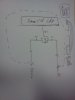
So I suggest a resistor of around 10k from the 8051 pin to the MOSFET's source (the +4V rail), a 270 ohm resistor from the 8051 pin to the MOSFET's gate, and a 5.1V (or 5.6V or 6.2V if you like) 0.5W zener diode with its anode to the gate and cathode to the source.

I did not have a 4V supply handy so tried a 5V instead. Below results are with 5V.
But this did not work. Test load(motor) did not switch off fully. However I tried two other quickies:
1. 220 ohm between VCC of MC logic to the 8051 pin : result was good and on/off was working correctly.
2. 220 ohm between Source and 8051 pin : result was motor was not fully off.

Note: 10K in place of 220 Ohm did not work.

Could you let me understand why above observation ? I would assume that changing load voltage to 5V should not matter as VGS will be 0V when both pin o/p and VSS are 5V.
But assuming at 0V MOSFET is not fully off(which it should be from transfer char) which explains load not fully off, in that case why the behaviour changes with experiment 1 above ?

Its puzzling me !!!!
 

KrisBlueNZ

Sadly passed away in 2015
Nov 28, 2011
8,393
Joined
Nov 28, 2011
Messages
8,393
I can't suggest any likely reason for those observations. My recommendation should work fine, with a 4V supply to the MOSFET or with a 5V supply.

So you were using a 5V supply for the 8051, and a separate 5V supply for the MOSFET source? How did you connect the two supplies together? By commoning the negative sides? That would be OK.

It sounds like a 10k pullup is too high; you say a 220 ohm pullup works OK. That doesn't make sense to me. Are you sure there's nothing else connected to the 8051's I/O pin?
 

dashy1981

Jun 19, 2013
83
Joined
Jun 19, 2013
Messages
83
Yes, 5V supply to both 8051 and MOSFET source, and I am using common ground as you already figured out.

There's absolutely nothing(not even the series resistor you suggested between pin and gate) connected between port pin and gate. On a seperaqte pin though I have one LED with a series resistor connected to VCC.

I have taken some measurements with 10K and 220 Ohm resistors. Possibly they may suggest something:

VCC(MC): 5.04V
VSS : 5.1V

1. With 220 Ohm between 5V rail and port pin
V(Gate) V (Drain) V(Source)
Pin High: 3.68 0.18 4.69
Pin Low : 0.37 4.15 4.18

2. With 10k between 5V rail and port pin
V(Gate) V (Drain) V(Source)
Pin High: 3.28 3.10 4.42
Pin Low : 0.11 4.19 4.21

Note I did not use any resistor in between gate and port pin, i guess that you suggested to limit the current. Will that matter much here ?
 
Last edited:

dashy1981

Jun 19, 2013
83
Joined
Jun 19, 2013
Messages
83
Tried one more thing... reduced VSS to 2 V and tried to measure gate current...

With 220 ohm, when port pin low : Ig= 3.4mA, VGS = 1.44V(Gate -ve wrt Source) : ON
With 220 ohm, when port pin high : Ig= -2.8mA(reverse current ?????), VGS= 0.58V(Gate -ve wrt Source) : fully off

With 10k ohm, when port pin low : Ig= 3.7mA,VGS = 1.58V(Gate -ve wrt Source) : fully ON
With 10k ohm, when port pin high : Ig= 0 mA,VGS = 1.1V(Gate -ve wrt Source) : partially ON


Looks like value of resistor matters !!! why... unable to understand.

but Strangely I seem to have some reverse current through gate!!!!
 

KrisBlueNZ

Sadly passed away in 2015
Nov 28, 2011
8,393
Joined
Nov 28, 2011
Messages
8,393
What is "VSS"? Is that the voltage rail that you're feeding into the source of the switching MOSFET? If so, you should call it something else - VSS is the name of the negative supply rail of the 8051! Call it VMS for "modem supply" or something like that.

Why does the switching MOSFET's source voltage vary so much during your tests? If it's being supplied from a 5V supply, whose negative rail is tied to the negative rail of the 8051 and the negative of your multimeter, it should be stable at 5V.

The lack of the gate series resistor won't cause this problem, but you should definitely add it, otherwise you're risking damage to the 8051.

I guess it's possible that either the MOSFET or the 8051 output have been damaged. Try disconnecting the 8051 pin completely, so there's just a pullup to the switching MOSFET's source, then the series resistor to the gate. If the motor still turns with a 10k pullup resistor, the MOSFET is faulty. If the problem goes away but returns when you connect the 8051 (with the pin driven to "1" by software), the 8051 is faulty.
 

dashy1981

Jun 19, 2013
83
Joined
Jun 19, 2013
Messages
83
VSS is the voltage at source wrt ground, VMS looks better as suggested :eek:

I guess it's possible that either the MOSFET or the 8051 output have been damaged. Try disconnecting the 8051 pin completely, so there's just a pullup to the switching MOSFET's source, then the series resistor to the gate. If the motor still turns with a 10k pullup resistor, the MOSFET is faulty. If the problem goes away but returns when you connect the 8051 (with the pin driven to "1" by software), the 8051 is faulty.

I could not undrestand it :confused:
Earlier i was connecting port pin --> R10K ---> source
Now if I disconnect it then where do the other end of R10K do we connect ?
Or you meant pull up from gate to VMS, so that VGS=0 and hence MOSFET shd be off in this case ? I did the later, and checked that with VMS=5V (and removing common ground so that MC ckt is totally disconnected) VGS is 1.13V and motor still turns on.
But connecting Gate directly to 5V rail, then the MOSFET turns off fully.

Does it indicate anything ?

Damage may have occurred as I was playing too much with them... :eek:
 

KrisBlueNZ

Sadly passed away in 2015
Nov 28, 2011
8,393
Joined
Nov 28, 2011
Messages
8,393
OK, this is what I'm suggesting.

attachment.php


The pullup resistor is tied to VDD, not VMS. You could do it either way.

The diode across the load isn't needed if the load is a modem, but should be present if you're powering a motor, as motors are inductive and generate back EMF which could damage the MOSFET.

The "X" marks the spot where you disconnect the MOSFET from the 8051.
 

Attachments

  • sch.jpg
    sch.jpg
    21.5 KB · Views: 197

dashy1981

Jun 19, 2013
83
Joined
Jun 19, 2013
Messages
83
Thanks Kris... Indeed as you suggested, looks like MOSFET is not functioning correctly. I replaced it with another and I see it functioning correctly. Now load current in off condition comes down near to zero while earlier it used to be around 25-30 mA. My device in the faulty case still was off as expected but I was worrying about the leakage may harm it.

But should I say the device faulty or still I can use it if that much leakage is tolerated by the circuit(not current use case) in general ???

PS: I checked it with the real use case with 4V supply the switch is working perfectly fine.... Thanks a ton to you !!!!!
 

KrisBlueNZ

Sadly passed away in 2015
Nov 28, 2011
8,393
Joined
Nov 28, 2011
Messages
8,393
Definitely throw it out. Semiconductors, and especially MOSFETs, can be damaged in ways that will show up later as more serious problems. For less than a dollar, it's not worth the risk. That's why I always get a few spares when buying cheap components - if you don't need them on the current project, they're ready for the next one.

You're welcome :)
 

dashy1981

Jun 19, 2013
83
Joined
Jun 19, 2013
Messages
83
One last question :
In another scenario I need to be able to switch USB connection on/off at times. I used the same ckt with below modifications(and without zener):
1. VBUS of micro USB cable coming out of PC connected to Source terminal directly.
2. Other end of VBUS wire connected to drain terminal directly
3. gate connections remain same as shown in your picture.

Now I am able to switch USB on/off but I do not understand why it should work !!!!
There's no common ground between Micro and MOSFET ckt.
Additionally, do I need to provide any safety components(zener/current limiting resistors) in this ckt ? i think may be zener is required but no
resistors are needed, since the load will draw only needed current as was the case when it was directly connected.
 

dashy1981

Jun 19, 2013
83
Joined
Jun 19, 2013
Messages
83
A pic should make it clear:
 

Attachments

  • ckt_usb.jpg
    ckt_usb.jpg
    118.9 KB · Views: 138

KrisBlueNZ

Sadly passed away in 2015
Nov 28, 2011
8,393
Joined
Nov 28, 2011
Messages
8,393
I recommend always using the zener directly between the gate and source. MOSFETs are too easily damaged by gate overvoltage without it.

There must be a common 0V connection between the micro and the 0V rail on the USB connection to the PC to complete the circuit. When the micro pulls its output down to its VSS rail, this needs to produce a negative Vgs for the MOSFET. So this VSS rail must be connected to the 0V rail of the USB cable so that the MOSFET's source will be positive relative to it.

I would also always use the pullup resistor (you can return it to the MOSFET source if you like) and the series resistor (to limit the current drawn from the micro when the MOSFET's gate-source capacitance).
 
Top