Maker Pro
Maker Pro

Female pin header on single-side PCB

Vagulus

May 6, 2018
26
Joined
May 6, 2018
Messages
26
I am working on a project based on an Arduino Pro Mini controller.
e000025_iso.jpg

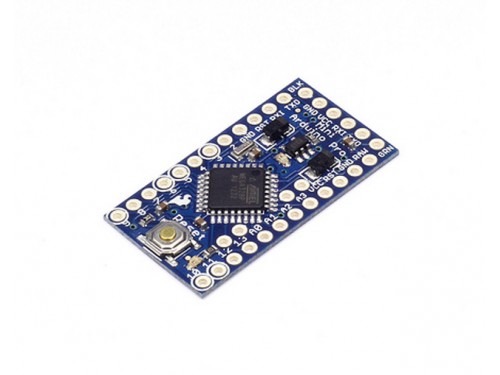
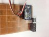
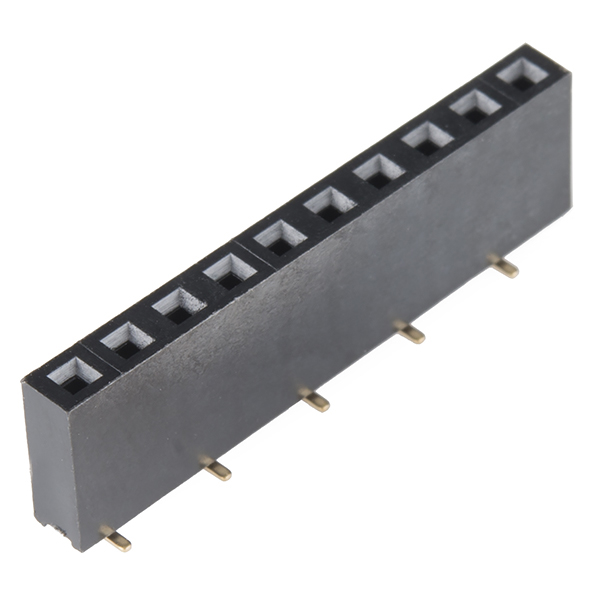
My idea is to have two 12-pin rows of male header pins soldered to the Pro Mini (on the long sides) which are to correspond to two 12-socket female headers on the PCB. Problem is that the design calls for a one-sided PCB and I can't see how I can solder the female headers (sockets if you will) to a one-sided PCB.

How can I get round this one?
 

Harald Kapp

Moderator
Moderator
Nov 17, 2011
13,728
Joined
Nov 17, 2011
Messages
13,728
I can't see how I can solder the female headers (sockets if you will) to a one-sided PCB.
Can you elaborate on the details of your 'problem'? Why would it be difficult to solder a female header to a one sided PCB?
 

Vagulus

May 6, 2018
26
Joined
May 6, 2018
Messages
26
Why would it be difficult to solder a female header to a one sided PCB?
Because the plasticized\ bit (the socket) sits on the copper where I want to solder. :( 
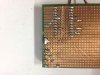
I could poke the pins through from underneath and have the Pro Mini on the opposite side of the board from the other components, but that would seem a bit odd. :confused:
 

davenn

Moderator
Sep 5, 2009
14,262
Joined
Sep 5, 2009
Messages
14,262
Because the plasticized\ bit (the socket) sits on the copper where I want to solder. :(


solder suck out the holes insert the strip of pins in place and then resolder the holes from the rear side

I'm assuming the holes go all the way through to the other side ?
 

Vagulus

May 6, 2018
26
Joined
May 6, 2018
Messages
26
solder suck out the holes insert the strip of pins in place and then resolder the holes from the rear side

Is that the only option? It sounds a bit hit and miss. ;) I guess the stick is to suck the solder through the hole. I'll give it a go. o_O
 

Harald Kapp

Moderator
Moderator
Nov 17, 2011
13,728
Joined
Nov 17, 2011
Messages
13,728
You can use a socket without plastic case like this one. After soldering the sockets in place, which is easily done from both sides or one side only, remove the carrier and insert the chip or whatever goes there.
 

Bluejets

Oct 5, 2014
6,927
Joined
Oct 5, 2014
Messages
6,927
Seems you've never seen veroboard.
Only been around for 50 years odd.
Available on Ebay for a few dollars and last lot I bought was a 5 piece pack.
 

Attachments

  • IMG_8891.JPG
    IMG_8891.JPG
    49.4 KB · Views: 77
  • IMG_8892.JPG
    IMG_8892.JPG
    50.7 KB · Views: 86

kellys_eye

Jun 25, 2010
6,514
Joined
Jun 25, 2010
Messages
6,514
Sounds like you're mounting the components on the copper side of the board SMD-fashion. You can easily bend the legs of a standard DIP socket outwards to solder to pads. If you want to be 'fancy' then design the board for the Arduino chip itself and solder ALL parts to it - not just the 'carrier board'.
 

Bluejets

Oct 5, 2014
6,927
Joined
Oct 5, 2014
Messages
6,927
Bit off topic here I know but just wondering why the pics I posted came up sideways?
 
Top