Maker Pro
Maker Pro

Finding the smallest possible actuator, or a new solution. Help massively needed!

GeorgeS1

Mar 26, 2016
6
Joined
Mar 26, 2016
Messages
6
Hello everyone,

I'm new to this forum and to electronics in general, so apologies in advance for being an absolute beginner in terms of knowledge. This forum has been super helpful, as have the people in it.

I'm trying to develop a piece of technology on a very, very small scale and am trying to find an actuator that will fit into the microscopic dimensions, or absolutely any other solution that can generate the type of telescopic motion i need. Here's a very rough sketch (apologies for the quality) of the dimensions that the actuator must fit in, and i'll describe it more below.

eg1.jpg
eg1.jpg
Essentially, what i need is to create a lifting motion from the 2x2x6 millimetre available to me, the motion needs to telescope out of the 6mil height to make contact with a very small mass above it. Almost like a microscopic hydraulic scissor lift. I realise that the answers coming back may be that this is absolutely impossible, so i'm prepared for that, but i really would appreciate any constructive advice. I have enough budget flexibility to get microscopic parts machined for purpose. Any other information i can provide, i will.

Thanks a million to anyone kind enough to help.

George.
 
Last edited by a moderator:

chopnhack

Apr 28, 2014
1,576
Joined
Apr 28, 2014
Messages
1,576
Is the 2x2x6 rectangular mass hollow or can it be made such to allow a thin bar to push up from below? The mechanism perhaps can be hidden below the rectangle?
Does the entire apparatus have to be hidden inside the 2x2x6 rectangle?
 

BobK

Jan 5, 2010
7,682
Joined
Jan 5, 2010
Messages
7,682
That is pretty challenging. Is it possible to have a flexible wire like the inside of a bicycle brake cable go through your 2x2x6 space with the actuator being larger and somewhere remote?

Bob
 

GeorgeS1

Mar 26, 2016
6
Joined
Mar 26, 2016
Messages
6
Is the 2x2x6 rectangular mass hollow or can it be made such to allow a thin bar to push up from below? The mechanism perhaps can be hidden below the rectangle?
Does the entire apparatus have to be hidden inside the 2x2x6 rectangle?

Thanks so so much for the response. The 2x2x6 dimension is the maximum outer dimensions for the actuator. A bar could be pushed up like you describe, but the mechanism pushing would have to fit into the small area, or within the area that the pylon is mounted on

eg2.jpg

Thanks again!

George
 
Last edited:

GeorgeS1

Mar 26, 2016
6
Joined
Mar 26, 2016
Messages
6
You could machine a small cam and use muscle wire to move the cam and create lift?
Adam

Thanks so much for the suggestion. I'm not sure what a cam is, really sorry for my current level of knowledge, could you describe that solution a bit more? Very grateful for the advice.

George
 

GeorgeS1

Mar 26, 2016
6
Joined
Mar 26, 2016
Messages
6
That is pretty challenging. Is it possible to have a flexible wire like the inside of a bicycle brake cable go through your 2x2x6 space with the actuator being larger and somewhere remote?

Bob

Thank you kindly for your input. A mechanic at work suggested something similar to this, so it may be helpful if i add further dimensions to my original post. The 'probe' (for want of a better word) is mounted on a 6mm diameter tube, so anything pushing a flexible mass through the probe would have to be driven through a 6mm diameter shaft. Any mass pushed through it would have to be capable of resisting some force without bending once in place.

Thanks again for your help,

George.
 
Last edited:

GeorgeS1

Mar 26, 2016
6
Joined
Mar 26, 2016
Messages
6
eg2.jpg

Here is an updated drawing with a rough estimation of the space available to drive the actuators from underneath, if any potential solutions require this.

Thanks in advance.
 

Arouse1973

Adam
Dec 18, 2013
5,178
Joined
Dec 18, 2013
Messages
5,178
Thanks so much for the suggestion. I'm not sure what a cam is, really sorry for my current level of knowledge, could you describe that solution a bit more? Very grateful for the advice.

George
Its like an egg.
 

Colin Mitchell

Aug 31, 2014
1,416
Joined
Aug 31, 2014
Messages
1,416
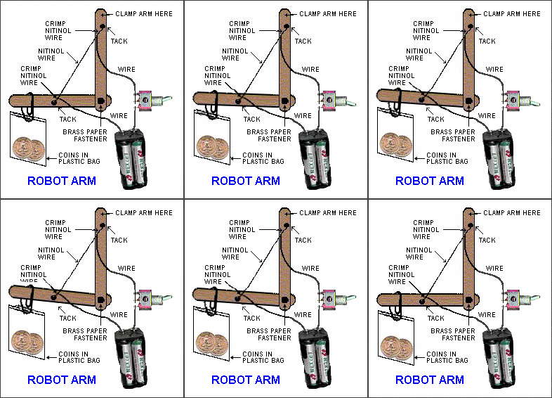
robotarm.gif
 

AnalogKid

Jun 10, 2015
2,893
Joined
Jun 10, 2015
Messages
2,893
What is the minimum travel distance required?

What is the minimum required force that the traveler must apply to whatever it contacts?

ak
 

Externet

Aug 24, 2009
891
Joined
Aug 24, 2009
Messages
891
Adding to the questions above; the material rising/extending has to be metallic or not ?; how many cycles are expected as life time ; how slow or fast to extend ?

I would put a cell phone micro motor (shaft horizontal) inside the 7mm diameter base and unwound a copper?* wire from its shaft exiting upwards inside the 2x2mm column that would behave as a guide.
Sort of a car power antenna, without the collapsing sections. No gears, the motor shaft unwinds/rewinds by polarity control.

*Or 1.5mm fishing line ? Other details as travel limiter/stops have to be implemented on the 'wire' thickness.
 

hevans1944

Hop - AC8NS
Jun 21, 2012
4,880
Joined
Jun 21, 2012
Messages
4,880
Given the maximum dimension requirements, this will clearly be a custom design. Piece of (expensive) cake once we know all the design parameters...

Could you provide information on the total stroke required, from fully retracted to full extended? How much force must the device exert on the "small mass" when it is extended and touching said mass? How fast must the telescoping part extend and retract? How often will it be extended and retracted? How many of the micro-actuators will be used simultaneously? Do the telescoping actuators need to move synchronously or independently? What is the operating environment? Air? Liquid? Vacuum? Will self-heating be a problem? How much temperature rise can you tolerate?

Your latest sketch shows three actuators mounted on a 7 mm diameter cylinder. Is this cylinder the 6 mm diameter tube you mentioned in post #8? Is this cylinder secured to a fixed, immovable base? Can (is) this cylinder hollow?

Do the actuators have to be inside rectangular telescoping tubes, perhaps to prevent rotation?

Others have asked similar questions, but I thought I would just get it all together in one post. If I have left out any design criteria, someone please chime in with more questions.

I like the push-wire design approach, perhaps with a linear piezo actuator as suggested by @chopnhack in his posts #2, 4, and 10. You can use flexible, stiff, wires (like piano wire) inside of brass guide-tubes with a 90 degree bend at the bottom of each tube. A plate could be soldered to the end of the 7 mm (6 mm?) support tube with holes drilled to accept the guide tubes. The piezo linear actuator would be attached to the protruding wires.

I doubt piezo linear actuators are cheap, but they are widely used as micro-manipulators, so the technology is sound and proven. If you want to explore other actuator possibilities, such as @Colin Mitchell's nitinol wire approach, that would be a very inexpensive design... although perhaps not as simple as he portrays.

Hop
 

Externet

Aug 24, 2009
891
Joined
Aug 24, 2009
Messages
891
I can see another simple way to accomplish the task, but at the first post we see one 'riser', no 7mm 'base'. Later we see three, a 7mm base Will there be multiple and more ? Will each riser have independent action/control, or all be simultaneous ?
Will there be other adyacent chambers ? Were will the control/(wires?) be housed/coming from ?
Drawings are decent as shown, but please name elements to refer to them properly in our suggestions and help you better.
Nice challenge !
 

hevans1944

Hop - AC8NS
Jun 21, 2012
4,880
Joined
Jun 21, 2012
Messages
4,880
... I have enough budget flexibility to get microscopic parts machined for purpose. Any other information i can provide, i will. ...

I have to ask this: what are you trying to DO? I realize you think you need a micro-lift to press against something. And maybe you need three of these, spaced some unspecified distance apart, perhaps mounted on a tube or solid rod of some sort. Or perhaps you need a bunch of these, arranged in a bed-of-nails array, to probe something. None of this describes the problem. It describes "a" solution to an unspecified problem and this "solution" might not be the best approach to solving the problem. So, please describe the problem, describe what you are trying to DO, not what you conceive to be the solution.

Here is an example description, in no way related to what you are trying to do:

Elmo has discovered that if the skin profile of certain species of frogs can be reproduced as an artificial "skin" there would be a huge Asian market for frog-skin gloves. Elmo has developed a polymer film that floats on water but needs to press this film against a (sedated) live frog's skin to transfer the skin profile to the polymer film. Elmo has a large supply of frogs, plenty of liquid polymer that will form a thin film when carefully poured onto a water surface, but now needs a way to press this film against the skin of the frog. Can anyone help Elmo design something (anything!) that will transfer the frog skin profile to the polymer film? The water is optional. An aerosol spray might work if it can be peeled intact from the (sedated) frog's skin. An electronic solution would be especially useful as Elmo also has a plentiful supply of electronic stuff.

Hop
 
Last edited:

hevans1944

Hop - AC8NS
Jun 21, 2012
4,880
Joined
Jun 21, 2012
Messages
4,880
Have you looked at a dot matrix printer mechanism?
Oooh! Those pins were great for making duplicate copies on multiple layers of paper, either with carbon paper between the copies or with micro-encapsulated ink on the copy's surface. I kinda liked the noise they made as they swooped across the pin-fed paper. They could make pretty decent gray-scale images too if you spread the image across a few dozen sheets of paper and stood back far enough to get the effect. I think I still have one tucked away somewhere in the basement, just in case. Unfortunately, I only have one computer left with a parallel Centronics printer port. But this project would need a custom electronics interface to the pin drivers anyway, so no big deal.

I was once tasked with the job of "printing" P-codes on classified negative copies of reconnaissance film. The P-code was just a series of consecutive numbers used to identify each "interesting" frame on a film roll as those frames were recorded in a log for later printing. At that time, each P-code was written in ink, by hand, on the image part of the frame.

When enlarged positive prints were made, the P-code stood out prominently and sometimes (apparently) obscured some details on the image. Of course an analyst (photographic interpreter or PI) was the person who applied the P-code in the first place, so they were careful not to "paint over" any important details. But try to explain that to a room full of VIPs, Generals, and maybe even the POTUS while giving your classified, cross-your-heart-and-hope-to-die, presentation. What this super high-tech photographic processing facility needed was some way to burn the P-code into the emulsion at the edge of the negative.

I did my dutiful research and found a company in nearby Indianapolis who used a Q-switched YAG laser with the beam focused down to an itty bitty spot, and a pair of x-y galvanometer mirrors, to draw with a vector character generator very tiny numbers, letters, and symbols onto just about any surface you can imagine, leaving behind perfectly etched permanent characters. They were quite proud of their ability to draw the characters along a circular arc to allow identification of ball-bearing race sets... even the ridiculously small ones used in precision rate gyroscopes. Except for the outrageous price and rather large size (the one I saw was apparently a prototype assembled on a large Newport Research optical bench), this seemed ideal. I took along a sample of exposed and developed film and they had no trouble burning "P1234" or something similar into the edge of the negative, outside of the image area but clearly visible even to the naked eye. Seemed like a done deal to me, just some more of my tax dollars working hard to keep America safe.

My boss at the time, who also happened to be the president of the company I worked for, had another idea. He had recently acquired a small calculator with a built-in thermal printer. Why not use that thermal print-head to burn the P-codes into the edge of the negatives? So we rigged up a prototype and began testing. Sure enough, if you drove the thermal print head hard enough it would burn through the emulsion and leave a visible P-code on the negative. If it was hot enough to burn through the emulsion though, it was also hot enough to melt the plastic film stock that supported the emulsion. When that happened, the film stock "welded" itself to the print head. Boss was very disappointed. He liked the laser tool, but thought it was too expensive and (probably) too dangerous to use while staring through a microscope at the film negative. I was unable to convince him that we could cost-effectively replace a human eyeball with a CCD camera, despite having demonstrated just that by using a pellicle beam splitter to present a micro-densitometer image to a CCD camera.

Sooo... maybe a dot-matrix print head, sans thermal... could be just the ticket to success.

Hop
 

dorke

Jun 20, 2015
2,342
Joined
Jun 20, 2015
Messages
2,342
I have to ask this: what are you trying to DO? I realize you think you need a micro-lift to press against something. And maybe you need three of these, spaced some unspecified distance apart, perhaps mounted on a tube or solid rod of some sort. Or perhaps you need a bunch of these, arranged in a bed-of-nails array, to probe something. None of this describes the problem. It describes "a" solution to an unspecified problem and this "solution" might not be the best approach to solving the problem. So, please describe the problem, describe what you are trying to DO, not what you conceive to be the solution.

Here is an example description, in no way related to what you are trying to do:

Elmo has discovered that if the skin profile of certain species of frogs can be reproduced as an artificial "skin" there would be a huge Asian market for frog-skin gloves. Elmo has developed a polymer film that floats on water but needs to press this film against a (sedated) live frog's skin to transfer the skin profile to the polymer film. Elmo has a large supply of frogs, plenty of liquid polymer that will form a thin film when carefully poured onto a water surface, but now needs a way to press this film against the skin of the frog. Can anyone help Elmo design something (anything!) that will transfer the frog skin profile to the polymer film? The water is optional. An aerosol spray might work if it can be peeled intact from the (sedated) frog's skin. An electronic solution would be especially useful as Elmo also has a plentiful supply electronic stuff.

Hop

LOL,
Your story reminds me of " How the Rhino got is skin" by Kipling.
kinda , tickle me Elmo and a 3 button "skin remover":)
 
Top