I once took a GCSE class in electronics back about 12 years ago, though I've forgotten a lot now, and am just getting back into it. Im working on a project to create a UID light or a rackable server I'm building... it needs to to the following:
Light or turn off an LED when a push button is pressed at the back of the server.
Light or turn off an LED when a push button is pressed at the front of the server.
Light or turn off an LED when told to do so from within the operating system on the server.
Due to availability and a desire for tidyness, I've opted to use a USB interface with the computer, connecting it to the USB headers on the mainboard. The USB port also supplies a nicely regulated power source.
I've never done this before, and so while searching around, I stumbled on a tutorial on creating a PIC based USB device that seemed almost ideal for my little project, using a 40 pin PIC 18f4550 - [link here]. I successfully built the device on a breadboard according the the given schematic, and successfully programmed it using the software provided. The device successfully connected to the PC, and running the proided executable, I was able to switch its LED on or off (or to be more acurate, toggle pin two between 5v and 0v from the computer), and I was able to read the value of a pushswitch at pin 3 (5v for open, and 0v for closed).
Programming is not my greatest skill (far from it!), and so I opted to bring this a step closer to what I wanted with the hardware rather than the firmware. I used a JK flip flop (which this forum helped me to get working - thank you) to divide its clock by two, using a switch for a clock pulse - so creating a push on/push off switch. I also connected pin 2 of the microcontroller to the clock of the flipflop via a diode so that the flip flop could be operated from either a push switch or from the computer. The flip flop's !Q output (which is either 5v or 0v... in theory) was connected back to Pin 3 of the PIC, replacing the switch...
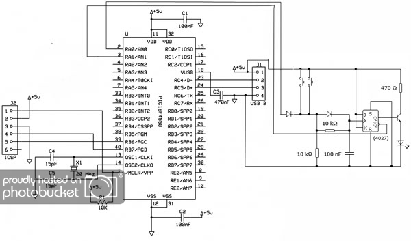
The microcontroller was successfully able to operate the JK flip flop on instruction from the computer to send a clock pulse from its pin 2, and was successfully able to read the LED state on the flip flop using the !Q input of the flipflop connected to the PIC's pin 3, which was reported back to the computer via USB... so far so good.
... my problem is that when I operate one of the push to make switch on the flip flop, the device unloads from the computer, and computer control is no longer possible... though the flip flop continues to work via the push switch input. Unplugging the USB connection and plugging it back in causes the device to be recognised once more, and makes computer control of the device once more possible ... untill one of the physical push switches is operated again.
Does anybody understand why?
Light or turn off an LED when a push button is pressed at the back of the server.
Light or turn off an LED when a push button is pressed at the front of the server.
Light or turn off an LED when told to do so from within the operating system on the server.
Due to availability and a desire for tidyness, I've opted to use a USB interface with the computer, connecting it to the USB headers on the mainboard. The USB port also supplies a nicely regulated power source.
I've never done this before, and so while searching around, I stumbled on a tutorial on creating a PIC based USB device that seemed almost ideal for my little project, using a 40 pin PIC 18f4550 - [link here]. I successfully built the device on a breadboard according the the given schematic, and successfully programmed it using the software provided. The device successfully connected to the PC, and running the proided executable, I was able to switch its LED on or off (or to be more acurate, toggle pin two between 5v and 0v from the computer), and I was able to read the value of a pushswitch at pin 3 (5v for open, and 0v for closed).
Programming is not my greatest skill (far from it!), and so I opted to bring this a step closer to what I wanted with the hardware rather than the firmware. I used a JK flip flop (which this forum helped me to get working - thank you) to divide its clock by two, using a switch for a clock pulse - so creating a push on/push off switch. I also connected pin 2 of the microcontroller to the clock of the flipflop via a diode so that the flip flop could be operated from either a push switch or from the computer. The flip flop's !Q output (which is either 5v or 0v... in theory) was connected back to Pin 3 of the PIC, replacing the switch...
The microcontroller was successfully able to operate the JK flip flop on instruction from the computer to send a clock pulse from its pin 2, and was successfully able to read the LED state on the flip flop using the !Q input of the flipflop connected to the PIC's pin 3, which was reported back to the computer via USB... so far so good.
... my problem is that when I operate one of the push to make switch on the flip flop, the device unloads from the computer, and computer control is no longer possible... though the flip flop continues to work via the push switch input. Unplugging the USB connection and plugging it back in causes the device to be recognised once more, and makes computer control of the device once more possible ... untill one of the physical push switches is operated again.
Does anybody understand why?