Maker Pro
Maker Pro

For what value of L, will this circuit resonate at 332kHz?

ubercool

Nov 6, 2012
27
Joined
Nov 6, 2012
Messages
27
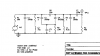
Hi I am working on a 332kHz beacon receiver. I have got the following circuit (pic attached). I have got the capacitor values but not the inductor values. Can anyone tell me what values of inductance will I need if I want this circuit to resonate at 332kHz?

Is there any specific formula to find out resonant frequencies of complex LC circuits like this one?
 

Attachments

  • Tank Circuit for 332kHz.jpg
    Tank Circuit for 332kHz.jpg
    42.7 KB · Views: 172

duke37

Jan 9, 2011
5,364
Joined
Jan 9, 2011
Messages
5,364
You need to post the entire circuit, you have components going nowhere.

It looks as if it might be a pair of tuned circuits, top coupled by the 15pF capacitor.

F= 1/(2*pi*(L*C)^0.5)), I presume you can rearrange this equation to get what you want, I would do it if I didn't feel so grumpy.:)
 

ubercool

Nov 6, 2012
27
Joined
Nov 6, 2012
Messages
27
Here's the complete circuit:

switches 2,3,5 of dip switch S2 are closed and switches 1,2,4,5 of dip switch S3 are closed
 

Attachments

  • scan0001 Tank Circuit for 332kHz.jpg
    scan0001 Tank Circuit for 332kHz.jpg
    86.4 KB · Views: 189

duke37

Jan 9, 2011
5,364
Joined
Jan 9, 2011
Messages
5,364
This is a pair of tuned circuits, top and bottom coupled. The tuned circuits differ one from the other so the terminating impedances will be different.

I would tackle this by calculating an approximate value of inductance and then simulating the circuit, using various values of inductance and terminating impedance to give the required bandwidth.

Do you have any idea of terminating impedance?

Are you trying to reproduce an existing circuit? The circuit as shown has top and bottom coupling and switched tunimg. If you only want 332kHz with one bandwidth the things can be simplified. I might have a go this evening if I feel up to it.
 

CDRIVE

Hauling 10' pipe on a Trek Shift3
May 8, 2012
4,960
Joined
May 8, 2012
Messages
4,960
Take a look at the attached screen shot. Study the parameters that were plugged into this filter design and post what you want them and this curve to look like. I've also attached a schematic of the filter that produced this curve.

Chris
 

Attachments

  • BPFcurve.JPG
    BPFcurve.JPG
    80.1 KB · Views: 180
  • BPFschematic.JPG
    BPFschematic.JPG
    26.2 KB · Views: 148

duke37

Jan 9, 2011
5,364
Joined
Jan 9, 2011
Messages
5,364
I have had a go with 5spice.
The first tuned circuit seems to do the business, the second is damped out of existance.

The second inductance is wierd!

The terminating impedances are important. The 15pF has a large effect on the frequency.
 

Attachments

  • Ubercool.png
    Ubercool.png
    8.4 KB · Views: 149
  • Ubercool 001.png
    Ubercool 001.png
    3.9 KB · Views: 147

ubercool

Nov 6, 2012
27
Joined
Nov 6, 2012
Messages
27
No sadly I dont have any idea of terminating impedance and yes I am trying to revive an existing circuit..the inductors have lost their value over time as this is a twenty five year old receiver. I just want to revive it by replacing the variable inductors with a fixed inductor as I want it to operaate on 332kHz only and not the complete band

This is a pair of tuned circuits, top and bottom coupled. The tuned circuits differ one from the other so the terminating impedances will be different.

I would tackle this by calculating an approximate value of inductance and then simulating the circuit, using various values of inductance and terminating impedance to give the required bandwidth.

Do you have any idea of terminating impedance?

Are you trying to reproduce an existing circuit? The circuit as shown has top and bottom coupling and switched tunimg. If you only want 332kHz with one bandwidth the things can be simplified. I might have a go this evening if I feel up to it.
 

ubercool

Nov 6, 2012
27
Joined
Nov 6, 2012
Messages
27
Thanks... can you tell me which software have you used for simulation?

Take a look at the attached screen shot. Study the parameters that were plugged into this filter design and post what you want them and this curve to look like. I've also attached a schematic of the filter that produced this curve.

Chris
 

duke37

Jan 9, 2011
5,364
Joined
Jan 9, 2011
Messages
5,364
As I said, I used 5spice for the simulation.

You could replace the filter with one designed with the program that Chris shows but you will need terminating impedances to get it right.
Where do the signals come from and where do they go? We may be able to guess the impedances.

You will not be able to use fixed inductors, they will need to be trimmed to the frequency you want..

I repair old valve radios sometimes so your radio is new! I have never met a faulty inductor unless someone has damaged it or the wires have corroded through so that it is open circuit. The phantom fiddler has much to answer for.:)

If the filter does not tune, it is much more likely to be problems with the multiple switch contacts, any one of which will affect the output. I would try using contact cleaner or bridge the closed contacts.
 

CDRIVE

Hauling 10' pipe on a Trek Shift3
May 8, 2012
4,960
Joined
May 8, 2012
Messages
4,960
No sadly I dont have any idea of terminating impedance

Unfortunately the source impedance and the terminating impedance form a key factor of filter design. Without this data it's impossible to design a bandpass filter. If you can post the complete schematic of the original device we may be able to guesstimate it.

Thanks... can you tell me which software have you used for simulation?

It was simulated in Tina by DesignSoft. There's a free version called Tina TI that can be found at the Texas Instrument pages or just Google Tina TI. I don't know if the TI version includes this option but I doubt it very much.

As a side note, this frequency is well within capabilities of active OpAmp filter design. ;)

Chris
 

ubercool

Nov 6, 2012
27
Joined
Nov 6, 2012
Messages
27
Here is the complete schematic...the input is coming from a RF amplifier MC1350P and it is going into another RF amplifier MC1350P. The tuning circuit is in between the two amplifier stages. Before the first RF amplifier, there is a tuning circuit which is an exact replica of the tuning circuit that is under discussion. The sequence is:

First tuning circuit->RF AMPLIFIER->Second tuning circuit->RF AMPLIFIER
 

Attachments

  • scan0002.jpg
    scan0002.jpg
    90.1 KB · Views: 162

CDRIVE

Hauling 10' pipe on a Trek Shift3
May 8, 2012
4,960
Joined
May 8, 2012
Messages
4,960
Are you trying to reproduce an existing circuit? The circuit as shown has top and bottom coupling and switched tunimg. If you only want 332kHz with one bandwidth the things can be simplified. I might have a go this evening if I feel up to it.

yes I am trying to revive an existing circuit..the inductors have lost their value over time as this is a twenty five year old receiver. I just want to revive it by replacing the variable inductors with a fixed inductor as I want it to operaate on 332kHz only and not the complete band

I repair old valve radios sometimes so your radio is new! I have never met a faulty inductor unless someone has damaged it or the wires have corroded through so that it is open circuit. The phantom fiddler has much to answer for.:)

If the filter does not tune, it is much more likely to be problems with the multiple switch contacts, any one of which will affect the output. I would try using contact cleaner or bridge the closed contacts.

There are times when I b!tch about people that seemingly post suggestions without reading through the thread. It would appear that I'm now guilty of this myself... SMACK!!!, WHACK, WHACK!! There, I just whacked myself.

I didn't realize that you have the existing circuit. What duke said is absolute fact. If we're talking about a marine beacon receiver that was used prior to LORAN and it didn't accidental go over the gunnels, I'd be spraying and working the switch with cleaner on the contacts. Don't worry about over-spray. It won't hurt anything. On the other hand, if it did find its way into salt water it's now an anchor. :p

Chris
 

duke37

Jan 9, 2011
5,364
Joined
Jan 9, 2011
Messages
5,364
I have had another look at the circuit, I have made the lower coupling capactor 1F to effectively take it out of circuit.

The Q is very, very high and in reality will have higher loss and wider response. You could trim it to get it nearer the correct frequency.

What is wrong with the inductances?
 

Attachments

  • ubercool 004.png
    ubercool 004.png
    10.7 KB · Views: 123
  • ubercool 005.png
    ubercool 005.png
    4.9 KB · Views: 108

CDRIVE

Hauling 10' pipe on a Trek Shift3
May 8, 2012
4,960
Joined
May 8, 2012
Messages
4,960
Duke, I think you were correct the first time. Redesigning his filter makes little sense.

Chris
 

ubercool

Nov 6, 2012
27
Joined
Nov 6, 2012
Messages
27
It was simulated in Tina by DesignSoft. There's a free version called Tina TI that can be found at the Texas Instrument pages or just Google Tina TI. I don't know if the TI version includes this option but I doubt it very much.

Chris

Hi I have downloaded TINA version 9...I cant find the option for filter design, should I go with simple AC analysis?
 

CDRIVE

Hauling 10' pipe on a Trek Shift3
May 8, 2012
4,960
Joined
May 8, 2012
Messages
4,960
Hi I have downloaded TINA version 9...I cant find the option for filter design, should I go with simple AC analysis?

It's 6 in the drop down list under "Tools".

Chris
 

duke37

Jan 9, 2011
5,364
Joined
Jan 9, 2011
Messages
5,364
I have a book (remember them?) by Arthur B. Williams, 'Electronic Filter Design Handbook'

I have calculated the component values for a Butterworth bandpass response and plotted the results using 5Spice.

You will need to make your own variable inductors and a signal generator to set the response.
 

Attachments

  • ubercool 007.png
    ubercool 007.png
    2.9 KB · Views: 169
  • ubercool 006.png
    ubercool 006.png
    8.8 KB · Views: 151

CDRIVE

Hauling 10' pipe on a Trek Shift3
May 8, 2012
4,960
Joined
May 8, 2012
Messages
4,960
I still don't see the point of this. If the original (switched bandpass) circuit still exists what's the point? :confused: You don't reinvent it. Just fix the damn thing!

Chris
 

ubercool

Nov 6, 2012
27
Joined
Nov 6, 2012
Messages
27
The thing is, I tried to repair it first but there was no reception at 332kHz in the positions of the switches I just mentioned in my previous posts but I could hear a tune on other positions of switches which brought me to the conclusion that the inductors and capacitors might have changed their values over time so I decided to replace the variable inductor with one single fixed inductor so that I can operate it over 332kHz..hence the redesigning :)

I again checked the values of capacitors today and the main 15pF capacitor is showing a value of 23pF on my LCR meter, do you think this might be the problem?

I still don't see the point of this. If the original (switched bandpass) circuit still exists what's the point? :confused: You don't reinvent it. Just fix the damn thing!

Chris
 

duke37

Jan 9, 2011
5,364
Joined
Jan 9, 2011
Messages
5,364
I agree Chris but he has not told us if he has b******d it.

The original circuit uses large capacitors and very small inductors. The circuit Q is very high and losses in the inductors will be important.
The bandwidth will be very small and a variable inductor will be necessary to tune the filter 'on the nose'.
If the 15pF capacitor is actually 23pF, this will drop the tuned frequency and adversly affect the response curve.

1. Did you have the correct switch connections?
2. Did you clean the switches?
3. Did you bridge the appropriate switch contacts?
4. What is the inductance of the inductors? You have a meter.

5. Do you have room to fit in a bodge?
6. Do you have a 332kHz accurate signal generator?
 
Top