Maker Pro
Maker Pro

Found problem in Kenwood KR-V95R

Quahlity

Mar 4, 2020
8
Joined
Mar 4, 2020
Messages
8
First time posting here.

I give my niece my Kenwood stereo only to find it wouldn't power up.
It had sat for a few decades on my basement floor.
Being an old lazy engineer I checked Google first and found this site.
EP seems to have better answers that 'Just buy a new one' so that was good.
However, nothing specifically for my stereo.

So I looked around inside it, and after a while found the two biggest caps were leaking. Also another right next to them. They are C44 and C45 (7500uF 71v) and C46 (3300uF 25v). They cost about $20 all together from China. I have about a two month wait for them, but unless they corroded the neighboring parts too much, that should be the fix. Time will tell.
 

Ylli

Jun 19, 2018
405
Joined
Jun 19, 2018
Messages
405
Are you sure it is leakage and not just the glue the factory uses to stabilize these larger parts? If the caps are not bulged and the 'leakage' is hard and dry, it is probably glue.

I wouldn't suggest getting those Chinese caps anywhere near the unit.
 

davenn

Moderator
Sep 5, 2009
14,260
Joined
Sep 5, 2009
Messages
14,260
So I looked around inside it, and after a while found the two biggest caps were leaking. Also another right next to them.

Are you sure it is leakage and not just the glue the factory uses to stabilize these larger parts?

totally agree


They are C44 and C45 (7500uF 71v) and C46 (3300uF 25v). They cost about $20 all together from China

I wouldn't suggest getting those Chinese caps anywhere near the unit.


agree again ... they are pretty crap

@Quahlity

please post a photo of the caps and what you think is leakage

I see by your IP that you appear to be in the NE USA, you should have been getting caps locally ... probably much cheaper
 

73's de Edd

Aug 21, 2015
3,622
Joined
Aug 21, 2015
Messages
3,622
Sir Quahlity . . . . .

I now THIRD the uber-high supposition / and / probability, of there being an initial misanalysis . . . . . on your part.

Schematic referencing of the design of that unit , reveals it being of circa 1980's vintage, and is using a V...E...R...Y . . . . . .S . . .L . . .O . . .W . . . 60 ~ up and down roller coaster ride , linear design type (LONG - life) of power supply for its + and - 71V supplies for the AUDIO POWER AMPLIFIER section.
Likewise, with the C46 and the +20 sub supply that it yields . . . . with it then begetting . . . two more + 13.5 and + 5.5 sub supplies , which will probably also be good.

In the interim time, awaiting for the arrival of your covid 19 laced "care package" from the FAR EAST you will have adequate time to have zeroed in on the units ACTUAL problem / fault(s) .

now . . . . . . . .HOWTODITOITINTHEDARKDEEPBACKWOODS . . . . . .

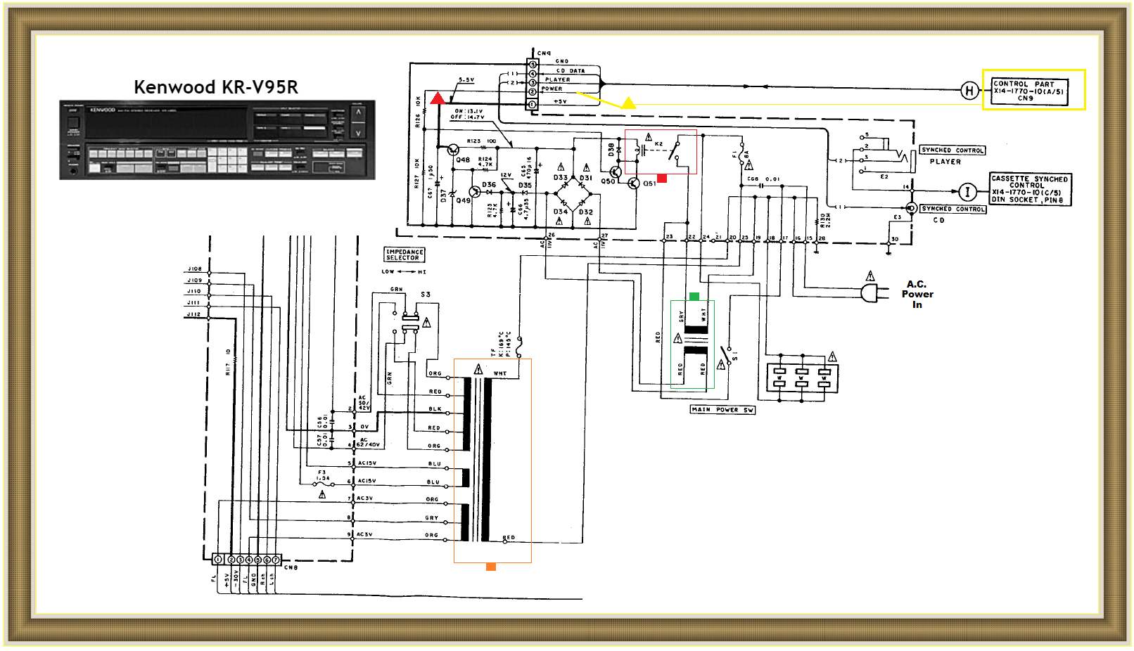
RELEVANT KENWOOD REFERENCING SCHEMATIC SNIPPETS . . . . .

Kenwood-KR-V95-R.png


After confirming all fuses being good . . . . and not having any being blowed-ed-ed.

AC power comes in at the right center and routes thru, a hopefully fully turned on switch S1, to the GREEN flagged standby transformer.
It supplies AC to the FWB- E-filter caps and regulator transistors above it and outputs +5.5 VDC frrom the final reg pass transistor of Q48. That RED TRIANGLE flagged 5.5 VDC feeds to the right to the YELLOW control board and if all is well when you attempt to turn on the unit, a small turn on voltage comes back down the YELLOW TRIANGLE line and into the base circuit of Q50 to 51 to activate RED flagged main power relay K2.
The power relay contacts of RED FLAGGED K2 then routes main AC power to the ORANGE flagged main power transformers RED and WHITE primary winding.
Now if all is well, one then checks the secondary windings and derived voltages from the secondary of the main power transformer.
UNLESS there is being a catastrophic failure present in the audio power output transistors section, or its power supply . . . . .in which case the control circuitry will respond by dropping that relay on voltage in an instant of the control circuitry having detected an overload fault .

Then you make a more in depth troubleshooting for shorted AUDIO output transistors, shorted power supply diodes , etc.


Thaaaaaaassssit . . . . .for now . . . .

73's de Edd . . . . .

Good health is merely being the slowest possible rate at which one can eventually die.


.
 
Last edited:

hevans1944

Hop - AC8NS
Jun 21, 2012
4,880
Joined
Jun 21, 2012
Messages
4,880
...So I looked around inside it ...
Wow! That's the very first step most of us here at Electronics Point take when troubleshooting "dead" electronics. But visual inspection must now always be followed by electrical testing, lest the troubleshooter waste expensive time and money replacing parts that don't need replacing. Hot melt glue has become the "go to" solution for holding pesky heavy electronics stuff in place because it saves a ton of labor that would otherwise be wasted on installing clamps, screws, nuts, washers, etc. I've even seen power transformers (albeit small ones) held in place with glue.

I can remember when 99 44/100% of the time, all the "troubleshooting" one needed to do was to find the vacuum tube whose filament wasn't glowing and replace that tube to effect a repair. <sigh> Those profitable servicing days are long gone.

In the old days, circa 1960 or so, I used the visual inspection time to blow away dust and to allow my oscilloscope, audio-frequency signal generator, and vacuum tube voltmeter to warm up and stabilize. Most vacuum tube test equipment is funny that way, drifting and bobbing up and down like a raft on the open sea until everything gets warm and toasty inside.

Today, almost all my test equipment is solid-state (transistorized, if you wanna use an older term) and is "instant on" with no warm-up necessary. Well, my el-cheapo Chinese LCD digital storage oscilloscope does have a "recommended" warm-up time of about one hour or so, but I leave it on all the time anyway when I am working on the bench. And my vacuum tube voltmeter disappeared about the same time that I misplaced my grid-dip meter, so since then I've gone through several multi-meters. I really like my Triplett Model 310 analog pocket-sized meters with their D'Arsonval meter movements and 20,000 ohms per volt sensitivity.
shopping

These were not much good for troubleshooting high-impedance vacuum tube circuits, and its annoying to have to pay attention to probe polarity when troubleshooting electronics with positive and negative supply rails, but I like 'em. I also really like my Mooshimeter, which is a fully floating multi-meter that I read using my iPhone.

My points are these: (1) Avoid Asian-sourced electronics parts from suppliers you haven't personally vetted, because otherwise you never know what you will get. Counterfeits and pure junk abound, so even a reliable supplier in the past may now be offering parts of dubious lineage and reliability. (2) Always at least check power supply voltages before deciding if anything is bad. I once spent hours "troubleshooting" a breadboard circuit that used op-amps, only to eventually discover that I had forgotten to turn on the ±15V DC power supply. (3) Either purchase or borrow some good test equipment.

You can get by (barely) with a digital multimeter purchased from a big-box home improvement store. Get one with at least 3-1/2 digits resolution. If this will be a one-time troubleshooting effort, consider adding an inexpensive oscilloscope kit. Available for less than thirty bux. Audio signal generators are a great way to insert test signals into audio amplifiers and such, but you can get by with using a laptop or desktop computer's sound output jack, along with some software you can write in Visual BASIC or download for free. Or just breadboard a 555 timer IC as a free-running oscillator powered from a 9V "transistor radio" battery. We will assume you already know how to do that, but if not... please ask!

We're here to help, so get busy doing some REAL troubleshooting using the suggestions offered by @73's de Edd.
 

Quahlity

Mar 4, 2020
8
Joined
Mar 4, 2020
Messages
8
Wow, 4 responses in less than a day. That's impressive. I appreciate all input.
I wanted to pull the caps out before responding. So that's done.

First I respect all your opinions regarding Chinese electronic parts. However, I've never had an issue with them, so I'm willing to (in your minds) risk it.

Ylli, the two big ones had the plastic top bulging, but that doesn't really mean much in this case. As to the leaking, considering only the neighboring parts corroded, I doubt it's glue. There is glue, but it's more than that. Once I had them out I could put the ohm meter to it, and then flipped and watched the reading go neg, then slowly climb. It's not a great test, but I have no other way to test them. That being said, only one of the big caps failed that test.

Davenn, Pictures to follow. Find those two big caps together under $25 and impress me :)

73's de Edd, That is a much better schematic than what I was working with, except it's not the right one. Would you happen to have the 'Power Amplifier unit' schematic? I have the parts list at least. The unit does have standby power, which this schematic shows. There are two power buttons, one which is a true power switch (S1), and the other is a power request button that activates the relay (K2) and powers the rest. This much of it is working, as I can hear the relay click and the 'Power Stand by' light is lit. Sorry I wasn't more clear about that before.

Havens1944, yeah. I was component level troubleshooting the first PC's (5150, 5160, and 5170 AKA the PC, XT and AT). I still have my Fluke and it still works perfectly. I rarely have the need to do any component level work anymore, so i prefer to throw parts at it, than to buy the equipment required to fully check each possible cause. Been a really long time since I've touched a tube, but I sure remember testing the ones from TV's at the local 7-11 when I was around 15.

Okay, so I hope I responded to everyone, sorry if I missed anything. That being said, now that the caps are out, and there is no more testing to be done. However, when cleaning the goo out, I found a 8.2v zener diode (D22) next to cap 46 had the lead completely corroded off. It's on order too. I'm sure it was required for proper operation :)

Pictures to follow.
 
Last edited:

Quahlity

Mar 4, 2020
8
Joined
Mar 4, 2020
Messages
8
The smaller cap. You can see the goo leaking down the side.
1 Leaking cap.png 2 Leaking cap.png

All the corrosion is adjacent to these caps.
3 Local corrosion.png

Slightly better view with the caps out.
4 Glue and corrosion.png

The corrosion was so bad diode's (D22) lead was completely gone.
5 Bad Diode.png

I can't find these parts on the schematic I have, which is odd, because I'm sure I did before.
Hope you enjoy the pics.
 

Ylli

Jun 19, 2018
405
Joined
Jun 19, 2018
Messages
405
Yup, definitely leakage. Parts in question are on the schematic pdf page 34 of 54.

Annotation 2020-03-04 220058.png
 

hevans1944

Hop - AC8NS
Jun 21, 2012
4,880
Joined
Jun 21, 2012
Messages
4,880
Havens1944, yeah. I was component level troubleshooting the first PC's (5150, 5160, and 5170 AKA the PC, XT and AT). I still have my Fluke and it still works perfectly. I rarely have the need to do any component level work anymore, so i prefer to throw parts at it, than to buy the equipment required to fully check each possible cause. Been a really long time since I've touched a tube, but I sure remember testing the ones from TV's at the local 7-11 when I was around 15.
Okay, welcome to the gray-bearded old farts club.:D Clean-shaven old farts welcome too.

It would have helped if I had known that history up front. I almost never try to teach old folks how to suck eggs. Still, it looks like your approach works and it probably saves a ton of time and money rounding up test equipment for a one-time repair job. Roger your Fluke still working fine. I've never been able to afford a Fluke, and I am on my second B&K Precision Chinese-made voltmeter. Like your Fluke, it still does the job for me. My Mooshimeter I purchased "just because" it was new, unique, and was offered at a good price that I could afford. I like to collect electronic toys that perform useful functions, but I must confess that after the novelty wore off I seldom use the Mooshimeter. I should probably remove the internal battery, lest it leak and destroy the expensive electronics inside.

Glad you found a reliable source for those Chinese parts. If one can tolerate the shipping delay, or afford the express air route, there are plenty of bargains available in Asia. As a kid (about 17 years old), I was on Okinawa where my father was stationed. I spent a lot of time at the Kadena AFB hobby shop, which was operated by a native Okinawan. This guy clued me in on Asian vacuum tubes, which we purchased a few miles away in Naha. Of course the transition to transistors was in full swing at the time, but we both were vacuum tube freaks. I think the tubes may have been made either in the USSR or Red China (as we called it), but also possibly Japan or Taiwan. Didn't much matter to me where they were made, they worked just fine and cost waaaay less than American branded tubes.

Please let us know here when you get that Kenwood stereo working again. And please post more pictures!
 

Quahlity

Mar 4, 2020
8
Joined
Mar 4, 2020
Messages
8
I'll post my success/failure when I get there. I admit that after reading your post that it made me wonder how cheap O-scopes were these days. It's hard to imagine that $70 can buy everything the Tektronix 100Mhz O-scope the company I worked for did and more and in color ... whoooooo hoooo! I might have to buy one just because it's "new, unique, and was offered at a good price that I could afford." I do that too, and sometimes it doesn't work out, but other times having that right tool for the job is like a miracle that makes fixing that obscure thing possible. Back when Hamfests were still a thing, I learned to stop buying stuff that you can't fit in your pocket, these handheld O-scopes fit that rule.
 

Quahlity

Mar 4, 2020
8
Joined
Mar 4, 2020
Messages
8
Using the full schematic, the caps are just filter caps for the separate power supplies. Tracing what that Zener does shows it is involved with a 3.0v supply that feeds IC1 and it is important to keep the power on after you let your finger off the power request button. I guess I miss actual troubleshooting, or I'm just lazy :)
 

shrtrnd

Jan 15, 2010
3,876
Joined
Jan 15, 2010
Messages
3,876
My belated input: Do you remember WHY the amp was on the basement floor for all of those years?
Do you remember if it had a fault when you stopped using it?
I've got a couple in my garage that I INTEND to get to some day, and the reason I took them out of service is that one
of the stereo channels went out, probably power transistors.
Just thought since you're waiting for parts, you might give some thought to why you stopped using that amp in the first place.
 

Quahlity

Mar 4, 2020
8
Joined
Mar 4, 2020
Messages
8
Yes yes. It's like the car battery thing that you find on the garage floor that doesn't work, but this isn't that. [blame that on magical cement :] I had upgraded from 2 channel to surround sound. I re-used the main speakers so had no more use for the stereo. The stereo is great, and was an early entry into the semi-conductor world. It has a graphic equalizer that also turns into a led light show while operating. It was hard to give up, but I regret nothing. Surround sound is like switching from black and white to color, easy not to make the change, but you can never go back once you have. You might imagine how elated I was that my niece got the old LP record bug and needed an amplifier.
 
Top