Maker Pro
Maker Pro

Gas(LPG) geyser help

bushtech

Sep 13, 2016
1,025
Joined
Sep 13, 2016
Messages
1,025
Geyser giving problems with the gas valve not being opened. The valve actuated by this electromagnetelectrom1.jpg

I have probed the red/black/yellow wires. Apparently 2 windings in here, one to pull it open and the other to keep it open.
Looks like red common and 6.9Ω to Black and 587Ω to yellow.

What I don't understand is I remove this magnet, clean contacts, replug and it will open the gas for a couple of times, sometimes just once, and then fail to actuate/open again.

This is the meaty bit of the electonics:
Totai top1.jpg

bottom1.jpg

Some cap not holding enough ooomph?

Rather baffled by this. Any insight appreciated
 

Harald Kapp

Moderator
Moderator
Nov 17, 2011
13,722
Joined
Nov 17, 2011
Messages
13,722
What I don't understand is I remove this magnet, clean contacts, replug and it will open the gas for a couple of times, sometimes just once, and then fail to actuate/open again.
Sounds rather obviously as if the contacts get non-conductive from environmental effects (corrosion?).The boards in your images don't look too clean, either.
  • Maybe encase the electronics in a sealed housing to protect from the environment (gases)?
  • Use a lubricant or contact grease to protect the contacts from corrosion.
 

bushtech

Sep 13, 2016
1,025
Joined
Sep 13, 2016
Messages
1,025
Thanks Harald
Yes, the board does not look very clean because I have depotted the board to get to the components. Remnants of the potting can be seen in top right hand corner. Contacts have been liberally cleaned with Lectro Kleen and worked a couple of times. System driven by 2 D cell batteries so seeing 3.1V on the power side.

I think I am now going to connect an analog MM over the incoming power to see if the 3.1V droops when geyser fires up
 

bushtech

Sep 13, 2016
1,025
Joined
Sep 13, 2016
Messages
1,025
No significant voltage drop detected when geyser firing up. Probably less than 0.1 of a volt
 

bushtech

Sep 13, 2016
1,025
Joined
Sep 13, 2016
Messages
1,025
I disconnected the electromagnet and connected two multimeters to R/B (high ohm) lines and R/Y (low ohms) lines.
Fired up the geyser and on the R/B line meter jumped around about 1 - 2.3V. R/Y showed no voltage

With a 587Ω coil and a 6.9Ω coil which one would be the actuating coil and which one the hold open one?
 

73's de Edd

Aug 21, 2015
3,622
Joined
Aug 21, 2015
Messages
3,622
With a 587Ω coil and a 6.9Ω coil which one would be the actuating coil and which one the hold open one?

Nobrainer 101 . . . . lesson
The low resistance one has the required OOOOOOOOOOOPH to initially pull in the solenoid, and activate the gas valve and then the former 587 Ω one (R.I.P ) is activated and takes over and supplies the meager magnetic hold in power then being required.
Then the unit heats until set up temp is reached and then the unit shuts down . . . . . . . .UNLESS . . . . . . . . there is lessening of gas pressure or burner flame out.
Then, the single black heavy wire in the foreground, identical and opposite the two like high voltage igniter / sparking wires that go to the to the burner from the ignition coil , is being connected to a high temp electrode that actually kisses the burner flame, for making conductive path to the frame of the grounded burner .
No flame presence then tells the unit to drop power to the solenoid to cut off the gas.
So you no get . . . . asfiinseeated . . . .aspinkseeated . . . .asssfeensatwed . . . asphyxiated. . .GASSED . . . .in the wee-wee morning hours, or else, house just go make BIG BOOOOOOM !

? . . . how gud is youse, with handling, uber fine, 42 gauge magnet wire, or checking its terminating ends wiring interfaces

Thaaaaasassssit . . . .
 
Last edited:

bushtech

Sep 13, 2016
1,025
Joined
Sep 13, 2016
Messages
1,025
Thanks a mil once again St Edd.I will go and recheck this tomorrow but for the time being I will assume that the varying 1-2.7 V is not enough to pull the solenoid open. Now to trace circuit and see
 

bushtech

Sep 13, 2016
1,025
Joined
Sep 13, 2016
Messages
1,025
There is a R0 bottom left on board. Some reddish line between the 2 contacts. Isn't a R0 normally a fuse? Not getting continuity if it is a fuse
 

73's de Edd

Aug 21, 2015
3,622
Joined
Aug 21, 2015
Messages
3,622
Somehow ? I initially read that as you having found the the 587Ω coil open ? . . . . .not so.
Since the unit has a plug, get two D cells, series arranged , and test the coils by hooking both coils up and then drop the
6.9 Ω coi connection and see if the solenoid holds . I expect it to be very slightly, compression spring loaded.
Can you then track down the wiring runs from the solenoids coil leads to the PCB and its traces ?
 

bushtech

Sep 13, 2016
1,025
Joined
Sep 13, 2016
Messages
1,025
The electromagnet seems OK. Do they fail?
Busy tracing. Red line leads to common of S8550 transistor.
Yellow line leads to single leg of Y2 transistor? through a 20Ω resistor to one leg of JD16-L IC. Further markings on it EPAUR0033. Battling to find a datasheet for this IC. Could it be a rotary encoder???o_O
 

73's de Edd

Aug 21, 2015
3,622
Joined
Aug 21, 2015
Messages
3,622
Sir bushtech . . . . . .

If this complete system / unit is SOLELY using 2 D cells (ANSWER ?)and with their combined 3VDC output, I am suspecting that the JD16-L IC is being a one of a kind custom design unit and just stuffed with Zetex transistors, as that is their all defining forté, in their making of effficient, low voltage use transistors.

The electromagnet seems OK. Do they fail?
Considering the equipment and the conservative power involved . . . vewy-vewy wawely . . ..

Could it be a rotary encoder???
Why ? what is there in that whole system that you perceive as being rotary in nature . . . . . and forbid . . . . that needs to be decoded ?

I don't know ALL of the JD16-L potentially possible internal functions, but I highly suspicion the need of the driving of that black ? Transformer ? beside it to create upwards of 200 'ish volts of output, that is then to fed across board to then be rectified by the blue cased HV diode, that is located beside the LARGE reddish brown poly cap.
That cap will be charged up and its charge cycles will then be repetetively dumped into the primary winding of the ferrite rod cored ignition transformer.
Voilà. . . .with a sparking at the secondary windings ends at electrodes at the burmer assembly . . . . the incoming gas is lit. The third wire sensing electrode detects flame presence, to shut down the gas valve in case of no flame developed initially or having a later flameout..
To the right of that cap is the Hi Voltage ignition coil, being all hermetically encased in STYRENE and has its high voltage secondary, being wound as six series aiding separate windings. Its 5K' ish . . .upwards ? . . . . outputted secondary voltage goes into the two imbedded black wires . . . likely being silicone, as they are going to the hot burner area.
(On that same topic, you have two braided WHITE wires in the units wiring bundle , does that pair also route to a thermally HOT area, as that might be braided fiberglass . . . . . . .since the 1930-1960's adhesive clumped asbestos wiring . . . .icht bin verboten !.Ja !

NOW BE MY EYES AND TELL ME :

Do you confirm that is being a quite small, black E-I cored transformer,that is located just to the side of that JD16-L IC ?
Then, on the other side of that t-former , can you also make out the cap value and voltage rating of the green poly cap ?
Also the numbering of the nearby TO-92 cased transistor, BUT don't break it, bending to see, as its being heavily encapsulated overall and at its wire lead base.
( Hint: A brite lite, used with a SHINY silver mylar foil strip (snack food mylar bag sourced) makes a GRE E E E EA A A A A T . . . . .a la Tony the Tiger . . . mini, CLOSE quarters inspection mirror.)
( It makes the normal, mini inspection or dental mirrors look like large CYCLOPS instruments. )

While you are on your roll, additionally check the marking on the only other seen, top side mounted TO-92 transistor, over near the earlier mentioned BIG poly cap and blue diodes area.

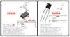
Busy tracing. Red line leads to ? common ? of S8550 transistor.

[Mod edit: changed NPN to PNP]
Here are your given PNP Y2 (S8550) surface mount) and NPN S8550 items specs.
upload_2020-8-11_3-15-22-png.49003


Puzzler ? . . . . . . I can see the non use of a continually running pilot light as on a pipe line natural gas, never ending feed.
Now with your . . . . maybe a decade . . . use of this unit ? does this unit have a low battery alarm, or do you have to treat it like a smoke alarm with annual replacements . . .(if not sooner).

Talk to me . . . . .


73's de Edd.....

Why is "abbreviation" being such a long word, in consideration of its definition ?


.
 

Attachments

  • upload_2020-8-11_3-15-22.png
    upload_2020-8-11_3-15-22.png
    109.8 KB · Views: 31
Last edited by a moderator:

bushtech

Sep 13, 2016
1,025
Joined
Sep 13, 2016
Messages
1,025
Thanks for the help St Edd, my guardian angel

Yes, powered by 2 D cells
A lot of the JD16-L I looked up were rotary encoders

The braided white wires run to two cutout(?) switches on combustion chamber and chimney.

Small black transformer has 7 legs

No markings on cap but 2 meters confirmed value as 24nf. No idea how to figure out the voltage:D

Transistor was easier to pull: X0605 VAST M9NJA

Only other transistor is the S8550 with another transistor tight up against it

?common? = collector

No low battery alarm, replace batteries when somebody complains of cold shower
 

73's de Edd

Aug 21, 2015
3,622
Joined
Aug 21, 2015
Messages
3,622
Sir bushtech . . . . . .
How about filling me in on how the unit responds to you, if you have it all hooked up again for normal operation.
Considering fresh D cells in the unit and propane / butane hooked up to it and being up to normal perational head pressure .
Say you then turn the units main power on, will its solenoid then activate the main gas valve and feed gas to the main burner . Then a stream of sparks from the electrodes at the burner , then ignites the gas and the burner bursts on, then there will be a timed drop out of the main solenoid , with the reduced power on the standby solenoid, then running the unit.*****

When the water comes up to the set temperature the system shuts down, until such time that water temp shift calls for the system to recycle, for a warm up.
( Unless this system is of the newer type that is fast heat up on demand and powering on by detection of a hot water valve being opened .

*****
UNLESS there is a flameout and the main burner looses its fire, then a sensing electrode, conducting via the flame to burner ground will deactivate the gas valve to shut the system down.

Now, how far does your system make this procedure . . . . . gas valve activates ? . . . . . sparks are made for ignition ? . . . . .the main burner ignites with a HEALTHY sized flame ? . . . . . .and then, slightly later, is when the flame goes out ?

There is a R0 bottom left on board. Some reddish line between the 2 contacts. Isn't a R0 normally a fuse? Not getting continuity if it is a fuse

Usually that is a zero 0hm jumper in a surface mount resistor case . . . . yours seems to be irrelevant and is thereby being left uninstalled.

73's de Edd . . . . .


.
 
Last edited:

bushtech

Sep 13, 2016
1,025
Joined
Sep 13, 2016
Messages
1,025
Thank you St Edd.
On opening a hot water tap unit responds by opening the gas and igniters supply spark, unit fires up and supplies hot water. Will continue like this until hot water tap closed. Currently I get the sparks but the gas supply not actuated, so no flame on
 
Top