Maker Pro
Maker Pro

Gould Model 465 Oscilloscope

fmevanspe

Oct 21, 2020
3
Joined
Oct 21, 2020
Messages
3
I have a Gould 465 DSO, 100 MHz. It was running fine when I left for lunch, but when I got back, the only thing running on the front panel was the power button indicator. Am I likely looking at the bridge rectifier having failed? The power supply has only one fuse that I can see and it tests ok. I've got it pretty well stripped down and I don't see/smell anything that would indicate a failed component. If there is a hidden fuse somewhere, that would be the next thing I'd check. It is completely dead except for that front panel light for the power button.
 

73's de Edd

Aug 21, 2015
3,622
Joined
Aug 21, 2015
Messages
3,622
Sir fmevanspe . . . . .


Why...why...why...and thats HEAVY on the why's . . . .are you being so fixated on the units bridge rectifier.
' Considerating ' . . .that the MAJORITY of those failures are related to junctions shorting . . .the adjunct fiter capacitors would not be happy at all, and PROTEST accordingly.

Now lets see if the same power supply was used in all of the GOULD 400 series.

Consult the supplied schema below and see if you have upwards of 24VDC being present
at the first filter served by that rectifier . . .as . . .C621.
Then see if the reduced ~14VDC supply is coming off the emitter of regulator Q601.
If so, the switch mode supply might actually be operating, so move on over to the outputted supply voltages and read across the cathode of D606 and across to the ground of the C611 first filter cap.
Standing by for your results . . . . . and / any / or further how do I done did dat ? related queries.

RELATED POWER SUPPLY SCHEMATIC . . . . .

GOULD-400-Series-Power-Supply.png


https://i.ibb.co/RvvhtcP/GOULD-400-Series-Power-Supply.png

73's de Edd . . . . .


Common sense is not a gift, it's a punishment.
Because you then find yourself having to deal with everyone who doesn't have it.


.
 
Last edited:

fmevanspe

Oct 21, 2020
3
Joined
Oct 21, 2020
Messages
3
I'm not fixated on the bridge rectifier...if the fuse had been blown, I would have immediately suspected a shorted capacitor.

I have a model 465, not a 400/420/450. The schematic I have is for the 400 series.

I did a more detailed components check in the power supply section. I found several caps that looked like they were leaking, so I removed them. They all tested ok with a Simpson 260 VOM. That doesn't accurately check the series resistance, but it would show a dead short.

When I pulled the three caps, the goo had literally eaten away the copper circuit foil and actually eroded the board itself! I don't see two of the three capacitors (C726 - 470uF/25V, and C729 - 1000uF/35V) on the 400 series schematics. I would like to have a schematic before I bridge the eroded copper traces. I am fairly sure that what is eroded was originally copper, but I'd prefer to be certain.

If you send me an email address, I can send you a photo of the corroded board (I'm not sure how to send a photo on the website). Without the copper, the electrons just can't get to where they need to be...

Frank
 

73's de Edd

Aug 21, 2015
3,622
Joined
Aug 21, 2015
Messages
3,622
Sir fmevanspe . . . . .

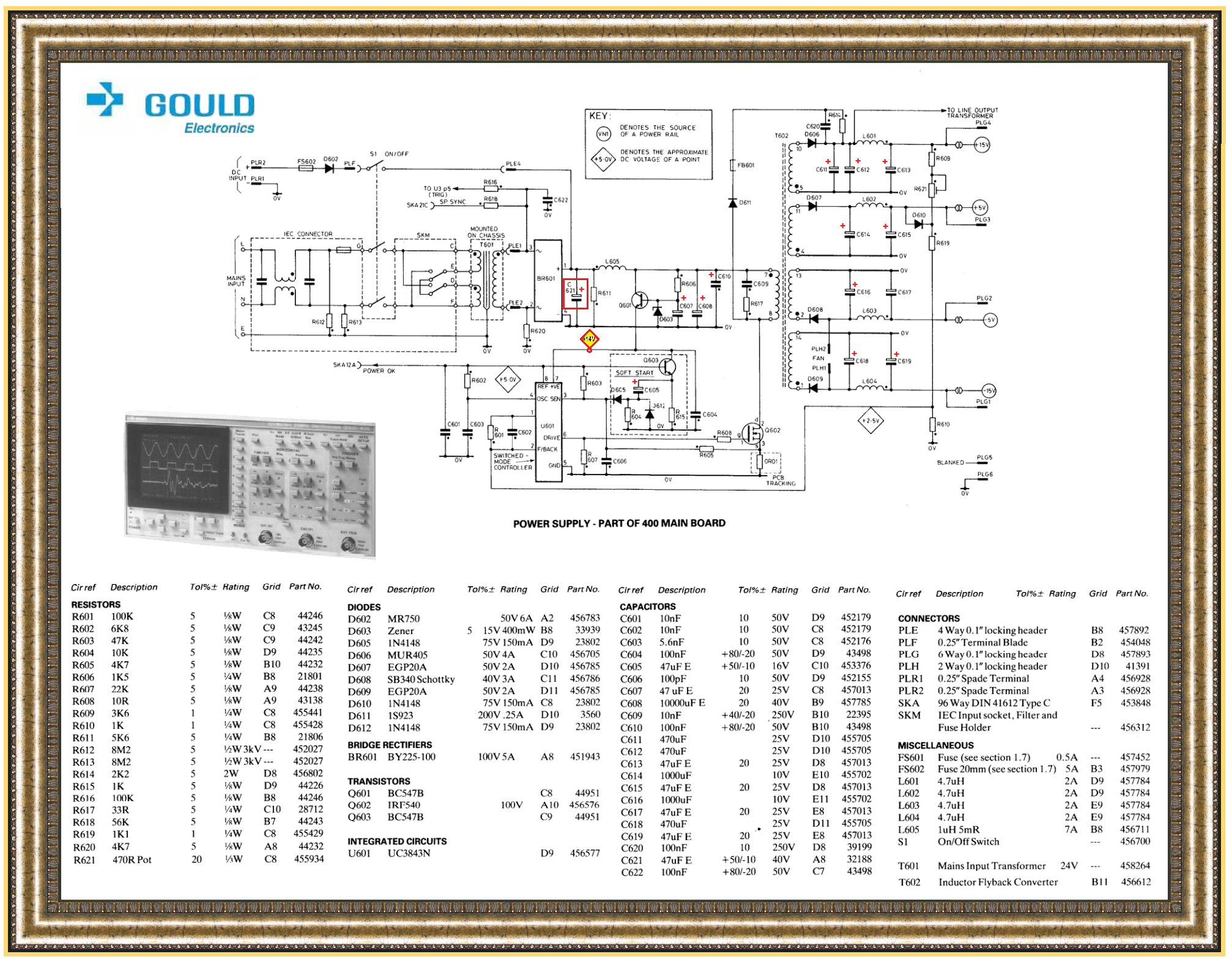
OH TAY ! on your forthcoming comments and the similarities / disimilarities of the supplied GOULD 400 series power supply . . .versus your 465 version.
I would at least suspect some high degree of carryover of their shared initial design aspects.

Now with your mentioning of electrolytic capacitors and the potential manufacturing window timeframe of your unit
Check out the supplied reference below with due concentration of particular interest to the series of 4 small silver colored mini aluminum-i-ninny-yum-yum can electroytics and their surface mount aspects with their black square molded plastic disc / spacers, that they are being mounted upon.

Now, with your FOUND marginal E-caps . . .any chance that they are of the type that you are encountering as being used in your unit ? ? ?
IF so . . . . . . . boy . . . . do I have some stories for you.

ALSO . . . since that power supply primary input is being a mere 24v . . . instead of a full 160-320 VDC that typical supplies use, any chance that the switch mode portion is operating, with you getting any DC voltages out of the 4 supplies on the far right side of the supply ?


REFERENCING . . . . ( It is being from a completely DIFFERENT other products circuit board)
But it uses BOTH sides of the board with its foil traces, and sometimes a fine trace is routed under /between one of those E-cap types pairs of terminals.


https://i.stack.imgur.com/2rMdM.jpg


ZUJ'ing ***. . . . . .
EatingPopcorn.jpg
. . . . . . . .for your reply . . . . .


***
https://en.wikipedia.org/wiki/Z_code

https://ham.stackexchange.com/questions/345/why-do-hams-often-conclude-messages-with-73


73's de Edd . . . . .


My wife queried me as to whether I thought that she was fat . . . . I then thought and tactfully replied " NO ! you're just being easier to see."
and then . . . . . W H I Z Z Z Z Z Z Z . . . . . . came the flying shoe.


.
 
Last edited:

fmevanspe

Oct 21, 2020
3
Joined
Oct 21, 2020
Messages
3
Here are a few pix of the board. The first pix shows the eroded copper trace. The second pix shows the three capacitors that weren't removed; they are the same as the three that were removed. The third pix shows the entire board.

I believe the photo makes it clear that the original copper trace was a "T' type connection. I can repair that and install new electrolytic capacitors...nothing unusual, 1000uF and 470uF at 35 to 50 volts.

I hope this repair works......
Gould 465 Scope Pix1-1.JPG Gould 465 Scope Pix3-1.JPG Gould 465 Scope Pix4.JPG
 

bertus

Moderator
Nov 8, 2019
3,325
Joined
Nov 8, 2019
Messages
3,325
Hello,

Was one of the capacitors leaking?
Then the acid from the capacitor could have caused the defect on the track.

Bertus
 
Top