Maker Pro
Maker Pro

hacking rc helicopter - need help

mikgol

Jul 6, 2013
87
Joined
Jul 6, 2013
Messages
87
Hey guys,

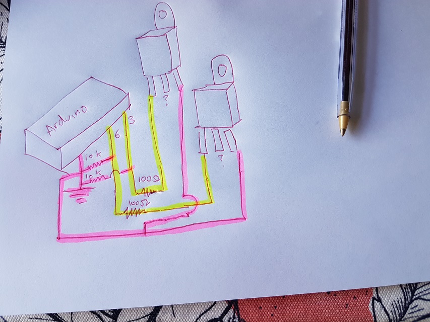
I'm hacking an old rc helicopter so that an arduino can power it. I wired the arduino up to the CEP83A3 (N-Channel Enhancement Mode Field Effect Transistor) that exists on the circuit board ...

http://web2.cet-mos.com/PDF/CET-MOS/TO-220-263-N/CET_CEP83A3.PDF

Im giving it PWM, which works up to about 90, but any higher than that and the arduino cuts out, so i'm guessing there's a voltage spike that happens with the high current motor.

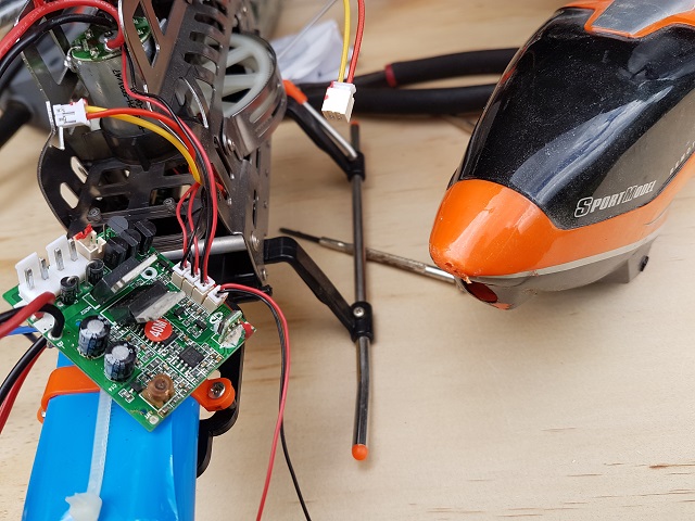
Do I need a diode somewhere? Or a capacitor? The circuit board already has capacitors so I thought it would be all good - here's a photo ...

w2gfn8.jpg
 

(*steve*)

¡sǝpodᴉʇuɐ ǝɥʇ ɹɐǝɥd
Moderator
Jan 21, 2010
25,510
Joined
Jan 21, 2010
Messages
25,510
Can you show us a circuit diagram, tell us the power requirements, and describe how you have bypassed the power to the arduino?
 

mikgol

Jul 6, 2013
87
Joined
Jul 6, 2013
Messages
87
Hey Steve, here's the circuit diagram ...

mufpcg.jpg


... the arduino sends PWM to the mofset via a 100 ohm resistors, with 10k resistors for ground.

Other than the 40mhz radio chip removed (don't want anyone hijacking chopper in the air), the circuit on the chopper end remains the same, with its capacitors etc.

Low PWM works great (I can rotate the blades at a slow speed) but anything higher and the motor stops turning.

My guesses:

1) voltage spikes?
2) the arduino isn't supplying enough current (remove the 100 ohm resistor and/or use a transistor between arduino and mofset)

What do you think? Thanks for your help mate, and happy Halloween!

Also, regarding power requirements, I measured the motors and they draw 7 amps each (it has 2 blades that spin opposite ways), but since i'm using the existing circuit it should handle this already - I just want to feed signal from arduino rather than the rf chip on it.
 

(*steve*)

¡sǝpodᴉʇuɐ ǝɥʇ ɹɐǝɥd
Moderator
Jan 21, 2010
25,510
Joined
Jan 21, 2010
Messages
25,510
I wrote a long reply to this, but it vanished :(

I'll try to get my thoughts together and post it later.
 

mikgol

Jul 6, 2013
87
Joined
Jul 6, 2013
Messages
87
You're a legend, thanks mate. I gotta say, this thing looks awesome starting up at low RPM, sounds like a real helicopter winding up. I'll post up a video of it once i can get it into the air
 

(*steve*)

¡sǝpodᴉʇuɐ ǝɥʇ ɹɐǝɥd
Moderator
Jan 21, 2010
25,510
Joined
Jan 21, 2010
Messages
25,510
OK, now I can see your diagram it makes both more and less sense... It was my last point in the post I lost, but it will be my first point here.

1) You need to learn how to draw circuit diagrams.

2) Your guess that the 100 ohm resistor might be the problem is a good observation. It is quite possible that the combination of this resistance and the gate capacitance gives a maximum switching rate for the mosfet. This would be consistent with the the maximum speed that you observe. If removing the 100R resistor increases the maximum speed, then you are on the right track. Your next step is a gate driver that can supply a much higher gate current. This problem would also likely cause the mosfet to get quite warm when the motor is running as fast as you can make it go.

3) another option is that you are switching on and off power to the motor controller. This is likely to cause problems (again, somewhat similar to what you observe). If this is a BLDC motor, the PWM to the power is unlikely to be the correct way to go. There should be some other interface that would accept a PWM signal or some other signal to control the speed. In this case mosfet(s) will not be required.

4) It is also possible that at a certain speed the voltage spikes are sufficient to reset the Arduino. I'm not sure the effect is exactly what you see, but it's not impossible. An easy solution here is to code up a pin to flash a LED at 1Hz or so. If the Arduino gets reset you should see this being interrupted.

It is very likely that you should have a reverse biased diode across the load. It is very likely that the load is inductive and this will cause huge voltage spikes as you switch it on and off.
 

mikgol

Jul 6, 2013
87
Joined
Jul 6, 2013
Messages
87
Hey Steve, thanks very much for your help and detailed post. Turns out the resistor was causing it - I removed it and all works good.

Around 140 PWM (out of 255) starts to lift it into the air. Next step is to install an accelerometer and start coding flight controls.
 
Top