Maker Pro
Maker Pro

Hall switch magnets.

NMNeil

Oct 3, 2014
111
Joined
Oct 3, 2014
Messages
111
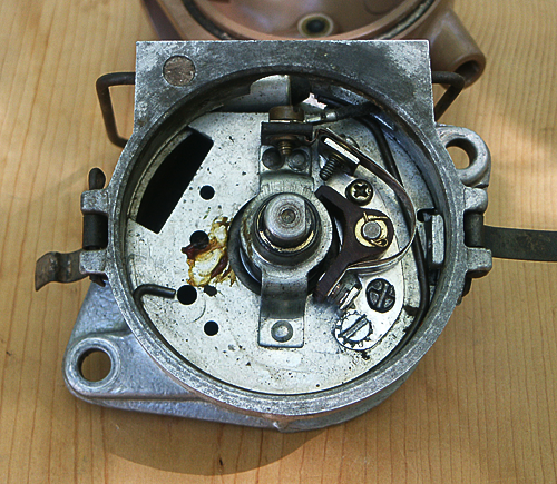
I've been messing around with the ignition system on my old Ford 8N tractor for a while now and the stumbling block in any design has always been the points. So I decided to build a hall sensor switch, possibly an Allegro A3144, because I already have a bag of them.
I made a PVC sleeve to go over the points cam and planned on drilling holes in the sleeve and epoxying in 3X2mm magnets at 90 degree intervals. The air gap could be anything but I was planning on about 1 to 2 mm.
Now the stumbling block. Despite an intensive search I have yet to find the grade of the magnets that are best for this application. I have a few 8x3mm N52 magnets that I'm using for testing but these are so strong that the sensor triggers long before the magnet is in front of the sensor, so it's going to be impossible to get an accurate and consistent trigger point, they are just too powerful. Ferrite and ceramic magnets don't come in small sizes, just the neodymium ones.
I have some 3x2 and 3x2mm N35 magnets on order for experiments, but I'm concerned that these will also be too strong. Anyone have any knowledge of hall sensors in real world applications that can steer me in the right direction?
 

Bluejets

Oct 5, 2014
6,922
Joined
Oct 5, 2014
Messages
6,922
I use 3 x 2 magnets and they work fine but I use a different Alegro hall switch. You may not be aware of an alternative method using the hall effect with the magnet secured to the back of the hall effect and sense a rotating metal vane. I think hall I use is A1102 (not sure I'll have to look) Alegro have details on the above method. 1 mm is about right for air gap.
 
Last edited:

NMNeil

Oct 3, 2014
111
Joined
Oct 3, 2014
Messages
111
I have looked at optical and hall sensors with a shutter wheel but my problem is that the distributor has a strap that supports a top bearing, so you can't fit a wheel. Using 90 degree spaced magnets is the only practical way that I can see.
Which hall sensor are you using?


front_view.png
 

NMNeil

Oct 3, 2014
111
Joined
Oct 3, 2014
Messages
111
Sorry, you already said that you are using the A1102.
Need more coffee
 

Alec_t

Jul 7, 2015
3,590
Joined
Jul 7, 2015
Messages
3,590
the distributor has a strap that supports a top bearing, so you can't fit a wheel
Looks like only 3 rivets hold the strap, and the plate they're on is held in by a circlip. It shouldn't be too difficult to get the plate out and remove the rivets and strap to enable fitting of a toothed wheel to the shaft. Then re-rivet the strap.
 

NMNeil

Oct 3, 2014
111
Joined
Oct 3, 2014
Messages
111
The only way it would work is if I replaced the strap and bearing with something that gave more clearance as there isn't room above the bearing. An awful lot of work, and I've thought of doing it, but it's beyond my capabilities so I'll stick with the PVC sleeve that I've made.
Plus I can take it back to original later if needed.
 

Alec_t

Jul 7, 2015
3,590
Joined
Jul 7, 2015
Messages
3,590
there isn't room above the bearing
Couldn't you fit a toothed wheel (with a square central hole) around the cam?
Or wouldn't Bluejets' suggested alternative method work simply using the original cam?
 

Bluejets

Oct 5, 2014
6,922
Joined
Oct 5, 2014
Messages
6,922
Now that I see a photo of your proposed install, perhaps you will need to re-think the location away from the hv distribution. In my experience any stray spark can jump into your nearby low voltage circuit( hall switch) and destroy it. What is the reason behind the proposed replacement?
 

NMNeil

Oct 3, 2014
111
Joined
Oct 3, 2014
Messages
111
The original distributor is mounted on the front of the engine and has the coil mounted to the top
serveimage

Not an ideal location for the regular points replacement and timing adjustment needed due to the very limited clearance between the distributor cap and the radiator.
naaenginelft.jpg

My plan was to set up the timing once and forget it, and change the coil for a standard automotive one and move it to a more sheltered location. The original coils were never the best and replacements are now only obtainable from Asian manufacturers and are of rather dubious quality.
Later I had plans to use a twin coil waste spark system to keep the plug wires very short and out of the way as well.
 

Bluejets

Oct 5, 2014
6,922
Joined
Oct 5, 2014
Messages
6,922
If you plan removing the HT then perhaps a manufactured/modified rotor could be your new base for the magnets.

I would in that instance be inclined to mount the magnets in something like a phenolic or bakolite base material in the form of a disc.

Magnets mounted in the peripheral face rather than the edge, would therefore have a natural tendency to stay put in the presence of centrifugal force.

One thing for future wasted spark arrangement is you will need 2 hall effect switches, one per dual coil.

I have never had any bother with standard points ignition though, other than initially have them burn out or rather, one point chews a lump out of the other. Replacement capacitor didn't make much difference but "vented" points did. They still remain in daily use in my 78 Celica today.
As for timing adjustments, other than a punctured vacuum advance diaphragm which I made a replacement from a Victa lawnmower carby diaphragm, never found the need to change the timing as it stays relatively in place.
 

Bluejets

Oct 5, 2014
6,922
Joined
Oct 5, 2014
Messages
6,922
Just thinking about that wasted spark arrangement, you may also need 2 separate discs, each with magnets @ 180 degrees apart , each discs magnets displaced 90 degrees from the opposing plate.
Physical position of each hall would need to be sufficiently spaced to avoid interaction form opposing channel magnets.
 
Top