Maker Pro
Maker Pro

Harman/Kardon HK6500. Loudness not working when button is pressed

KrisBlueNZ

Sadly passed away in 2015
Nov 28, 2011
8,393
Joined
Nov 28, 2011
Messages
8,393
Q442 and Q444 are the main output transistors for the right channel. They drive the right speaker. They should be mounted onto a big heatsink. Q441 and Q443 are the output transistors for the left channel.

OK, I need more accurate measurements of the voltages across R555 and R556. Set your multimeter to the 2V range so it will show more digits.
  • Disconnect CN401 and CN402
  • Power on
  • Measure and record voltages across R555 and R556
  • Power off
I also need the voltages across four more resistors. Find the following components on PCB 9, "tone control board":
R539 and R541 (near Q515 and Q517)
R540 and R542 (near Q516 and Q518)
  • Set multimeter to 20V range
  • Reconnect CN401
  • Power on
  • Measure and record the voltages across those four resistors - R539, R541, R540 and R542.
  • Power off
 

Rickedafied

Aug 3, 2014
126
Joined
Aug 3, 2014
Messages
126
KrisBlueNZ said:
Q442 and Q444 are the main output transistors for the right channel. They drive the right speaker. They should be mounted onto a big heatsink. Q441 and Q443 are the output transistors for the left channel.

OK, I need more accurate measurements of the voltages across R555 and R556. Set your multimeter to the 2V range so it will show more digits.
  • Disconnect CN401 and CN402
  • Power on
  • Measure and record voltages across R555 and R556
  • Power off
I also need the voltages across four more resistors. Find the following components on PCB 9, "tone control board":
R539 and R541 (near Q515 and Q517)
R540 and R542 (near Q516 and Q518)
  • Set multimeter to 20V range
  • Reconnect CN401
  • Power on
  • Measure and record the voltages across those four resistors - R539, R541, R540 and R542.
  • Power off
With CN401 and CN402 disconnected, R555 and R556 both showing 0.00V

With CN401 connected alone,
R539 shows -3.19V
R540 shows 3.19V
R541 shows 3.20V
R542 shows -3.16V
 

KrisBlueNZ

Sadly passed away in 2015
Nov 28, 2011
8,393
Joined
Nov 28, 2011
Messages
8,393
OK. The tone control section is drawing about 50% more current than it should. This could be why the Q519/Q520 heatsink is getting too hot.

I missed out some steps from my step-by-steps in post #101. Can you make some more measurements? I want to know the voltages across R555 and R556 with only CN401 plugged in, then only CN402 plugged in.
  • Disconnect CN401 but leave CN402 plugged in
  • Power on, measure and record voltages across R555 and R556, power off
  • Reconnect CN401 and disconnect CN402
  • Power on, measure and record voltages across R555 and R556, power off
Edit: Make sure that the wire that goes into CN401 goes to the tone control board, and the wire that goes into CN402 goes to the "BASCON" board.
 

Rickedafied

Aug 3, 2014
126
Joined
Aug 3, 2014
Messages
126
section is drawing about 50% more current than it should. This could be why the Q519/Q520 heatsink is getting too hot.

I missed out some steps from my step-by-steps in post #101. Can you make some more measurements? I want to know the voltages across R555 and R556 with only CN401 plugged in, then only CN402 plugged in.
  • Disconnect CN401 but leave CN402 plugged in
  • Power on, measure and record voltages across R555 and R556, power off
  • Reconnect CN401 and disconnect CN402
  • Power on, measure and record voltages across R555 and R556, power off
Edit: Make sure that the wire that goes into CN401 goes to the tone control board, and the wire that goes into CN402 goes to the "BASCON" board.
Ok the tone board must be the board with the bass, treble and ballance. And the bascon board is the board with the loudness, subsonic, stereo/mono and external processor switches right?
 

Rickedafied

Aug 3, 2014
126
Joined
Aug 3, 2014
Messages
126
With CN402 plugged in alone,
R555 and R556 showing -0.12V

With CN401 plugged in alone,
R555 showing -0.42V and R556 showing -0.41V
 

KrisBlueNZ

Sadly passed away in 2015
Nov 28, 2011
8,393
Joined
Nov 28, 2011
Messages
8,393
OK. The tone control board is drawing at least twice as much current as it should, and this is why Q519 and Q520 are getting too hot.

Rather than starting to replace the transistors on the tone control board, I suggest some radical surgery - remove all 18 transistors, and install two ICs instead. You would also need one capacitor for each IC. There is an IC that is perfect for this application: OPA604. It's available from Digi-Key for USD 3.05 each: http://www.digikey.com/product-detail/en/OPA604AP/OPA604AP-ND/251162

This change would reduce the current to about 1/4 of what it is now.

Each IC would need to connect to five points on the board. I can draw up a connection diagram.

If you want to take this route, remove all eighteen transistors from the tone control board and post a good clear photo of each side of the board, square-on, so I can line up both sides of the board and draw up a connection diagram. And you might as well order two of those ICs and two of these capacitors: http://www.digikey.com/product-detail/en/R82DC4100AA60J/399-5860-ND/2571295
 

Rickedafied

Aug 3, 2014
126
Joined
Aug 3, 2014
Messages
126
OK. The tone control board is drawing at least twice as much current as it should, and this is why Q519 and Q520 are getting too hot.

Rather than starting to replace the transistors on the tone control board, I suggest some radical surgery - remove all 18 transistors, and install two ICs instead. You would also need one capacitor for each IC. There is an IC that is perfect for this application: OPA604. It's available from Digi-Key for USD 3.05 each: http://www.digikey.com/product-detail/en/OPA604AP/OPA604AP-ND/251162

This change would reduce the current to about 1/4 of what it is now.

Each IC would need to connect to five points on the board. I can draw up a connection diagram.

If you want to take this route, remove all eighteen transistors from the tone control board and post a good clear photo of each side of the board, square-on, so I can line up both sides of the board and draw up a connection diagram. And you might as well order two of those ICs and two of these capacitors: http://www.digikey.com/product-detail/en/R82DC4100AA60J/399-5860-ND/2571295
So either i replace them all or go with two IC components and capacitors?
Is it possible only one of them is bad and I can find it by testing them some how? If not, how did this happen? Is it a design flaw, or is it because Q519 and Q520 can't handle it?
 

Rickedafied

Aug 3, 2014
126
Joined
Aug 3, 2014
Messages
126
Are they all the same type transistors on the tone control board? Would new ones still make the heatsink overheat?
 

KrisBlueNZ

Sadly passed away in 2015
Nov 28, 2011
8,393
Joined
Nov 28, 2011
Messages
8,393
The problem is not that Q519 and Q520 "can't handle" the current. They are being forced to generate about 2.6 watts (total) in heat energy, and I have to assume that the heatsink can't dissipate this energy, because it's getting a lot hotter than it should.

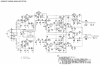
The reason why Q519 and Q520 are generating so much heat seems to be that the tone control board is drawing too much current. It is drawing 42 mA. But I can't be sure how much it is supposed to draw. That information is not shown on the diagram. I believe it's supposed to draw less than that, based on the voltages across R539~542 which relate to one part of the tone control circuit. According to the schematic, they should be about 2.1V which corresponds to a current of 12.7 mA total, but you measured them at about 3.2V in post #102 which corresponds to about 19.3 mA in that part of the circuit.

The remaining 22.7 mA (to make up the total of 42 mA that the board is drawing) must be being drawn by other parts of the tone control circuit. But trying to figure out exactly where, and why, those currents are flowing is not worthwhile, which is why I suggested replacing the whole lot with two ICs.

I would like to say that the transistors in the tone control circuit have been damaged, or are failing due to age, but both the left and right channels have the same high current flow, and they're independent of each other. So if it's a component failure, it's identical in both channels, which seems unlikely. The alternative is a design problem, but then that heatsink would have been getting hot ever since manufacture, and that would have left signs on the circuit board.

So I'm really not sure what the problem is.

If you like, you can replace all of the transistors on the tone control board and see what happens. While they're out of circuit, you could also measure the resistors, just in case some of them have drifted in value and are causing the high current problem. You can also replace the electrolytic capacitors.

There are four types of transistors on the tone control board:

Q501,503,505,507,511 (left channel) and Q502,504,506,508,512 (right channel) are 2SC2320 and can be replaced by MPSA05: http://www.digikey.com/product-detail/en/MPSA05G/MPSA05GOS-ND/1482444

Q509,513 (left) and Q510,514 (right) are 2SA999 and can be replaced by MPSA55: http://www.digikey.com/product-detail/en/MPSA55G/MPSA55GOS-ND/1482498

Q515 (left) and Q516 (right) are 2SB646 and can be replaced with MPSA55 as well

Q517 (left) and Q518 (right) are 2SD666 and can be replaced with MPSA05 as well.

So to summarise, use MPSA05 for Q501~508,511,512,517,518 (12 transistors) and use MPSA55 for Q509,510,513~516 (six transistors). These ALL have different pinouts from the originals.

There are also two diodes on the tone control board - D501 and D502. They are both listed as 1S2473 which is an obsolete type, but they can be replaced by any small signal silicon diode such as the 1N914: http://www.digikey.com/product-detail/en/1N914/1N914FS-ND/978749

Replacing these semiconductors may or may not reduce the current drain and stop the heatsink from overheating. As I said, take the opportunity while the transistors are removed to measure all of the resistors. If any resistor doesn't measure within ±5% of its marked value, post the circuit reference, the marked value, and the measured value (measure in both directions). In some cases the other components in the circuit may affect the measured value. But with the transistors removed, this will be minimised.
 

Rickedafied

Aug 3, 2014
126
Joined
Aug 3, 2014
Messages
126
Wow. I never thought this loudness button would be so much work lol. Maybe i should have left it alone and just figured out why those 8 other transistors are getting hot, but I really want that loudness button working properly.

I'm going to remove all the transistors from the tone control board and test the resistors like you said. I don't know how to read the bands by memory so that's gonna be fun looking them up.

I dont have a credit card to be ordering online so I'm gonna have to go see if that electronic store has the ICs and capacitors you mentioned.

I still have that phono circuit board that is mounted side ways, disconnected. I know that's another issue, but I just noticed that it looks like someone used a screw that was too long for attaching the outside cover. It looks like the screw drilled straight through the board and cut off circuits and possibly shorted out components. I wonder if that's why the transistors on that board were getting hot. Does the schematic show any other connections to the main board instead of CN403? Or connections passing to the tone control board that could have shorted out some of its components?
 

KrisBlueNZ

Sadly passed away in 2015
Nov 28, 2011
8,393
Joined
Nov 28, 2011
Messages
8,393
It's ironic, because there isn't even anything wrong with the loudness circuit! All of these other problems are in other parts of the amplifier.

You probably won't find that IC outside of Digi-Key and Mouser. It's not a common component. Standard op-amps aren't suitable because (a) many of them are not designed for low distortion, and (b) most of them are not rated to operate from ±22V (or it's at the absolute limit of their voltage ratings).

The phono board only gets power through JL601, which connects over to CN403 on the main board. There are no other power feeds to the phono board. And the supply rails on the tone control and bascon boards are regulated separately from the phono board's supply, so I don't think that a fault on the phono board would have damaged the tone board or the bascon board.

Can you upload some photos of the board damage caused by the long screw?

I've attached the schematics to this post. I had to paste these together from many A4 pages of scans that were in the service manual I found. Not everything lines up perfectly. And the scans weren't very good to start with. Many of the numbers are hard to read. But it's better than nothing.
 

Attachments

  • epoint 269932 Harman Kardon HK6500 schematic main 4bc.png
    epoint 269932 Harman Kardon HK6500 schematic main 4bc.png
    838.6 KB · Views: 1,826
  • epoint 269932 Harman Kardon HK6500 schematic phono section 4bc.png
    epoint 269932 Harman Kardon HK6500 schematic phono section 4bc.png
    495.8 KB · Views: 2,281

Rickedafied

Aug 3, 2014
126
Joined
Aug 3, 2014
Messages
126
Ok, and thanks for putting the schematics together and posting it.
I checked continuity for the circuits that look damaged and it shows the tuners Right channel has been cut off. On the other side of the board, it didnt drill into any component, but C702 looks black on the board under it. I guess those circuits got grounded by the screw
 

Attachments

  • DSCN0262.JPG
    DSCN0262.JPG
    236.8 KB · Views: 305
  • DSCN0271.JPG
    DSCN0271.JPG
    158.2 KB · Views: 267
  • DSCN0267.JPG
    DSCN0267.JPG
    179.8 KB · Views: 384

KrisBlueNZ

Sadly passed away in 2015
Nov 28, 2011
8,393
Joined
Nov 28, 2011
Messages
8,393
You're right, that hole is not going to do any harm apart from cutting out one channel on one input. To fix it, first clean up the crumpled copper. Use a large drill bit, pressed gently into the hole on the copper side, and twist it so it leaves the edges of the hole clean. Or use a razor blade or scalpel to do the same thing. Clean up the whole area using a cotton swab and isopropyl alcohol or any other solvent. Then scrape off some of the solder mask that's covering the bits of copper you need to join together, and join them by soldering on an off-cut resistor lead or similar.

OK. Do you want to find out what's wrong on the phono board? This is only important if you have a turntable, or want to be able to use a turntable in future. Otherwise you can just remove the ribbon wire from JL601 (phono board) to CN603 (main board) and the other inputs will work.

If you don't care about the phono stage not working, skip the rest of this post.

If you do want to fix the phono amplifier, start by posting complete pictures of both sides, viewed from directly above so I can align the top and bottom with each other.

The pictures you've been posting so far are good, but I would like to see a complete image of both sides of the board.

When you test the phono board, connect the wire into CN403, power up, measure the voltages, and power off. We don't want to damage anything unnecessarily. Also, leave the phono board disconnected when you're working on other parts of the unit. It is loading down the power supply rails and this could affect the power amplifier (not damage it; just affect it).

Start by measuring some voltages.
  • Voltages across R637 and R638
  • Voltages (measured relative to circuit ground/common) on base, collector and emitter (from left to right) of Q613
  • Voltages on base, collector and emitter of Q614
  • Voltage on cathode (stripe end) of D601
  • Voltage on anode (opposite stripe end) of D602
  • Voltage on collector (middle pin) of Q703
Also visually inspect Q613~616 for signs of overheating, solder shorts, etc, and note anything else that you notice while examining it (apart from the screw hole which we already know about).
 

Rickedafied

Aug 3, 2014
126
Joined
Aug 3, 2014
Messages
126
R637 shows 2.35V
R638 shows 1.33V

Q613 shows,
B 44.7V
C 17.5V
E 46.7V

Q614 shows,
B -45.3V
C -17.6V
E -46.1V

D601 Cathode shows 18.1V
D602 Anode shows -18.1V

Q703 Collector pin shows 14.3V

Q613 and Q614 are the only components that are getting real hot on the board. There are no shorts or cold solder that I can see.
 

KrisBlueNZ

Sadly passed away in 2015
Nov 28, 2011
8,393
Joined
Nov 28, 2011
Messages
8,393
Thanks for the photos. They're all good but some of them have "bloom" from reflections of the light source. It's best to take them outside in indirect light. But it doesn't matter in this case. I don't think I need to know much about that board. The overviews of the top side are good for giving me a general idea of things.

I can see the discoloration around C702. I don't know what it is, but I don't think it's a problem.

The voltages are OK.

The positive regulator, Q613, is passing 50 mA and is dissipating nearly 1.5W.
The negative regulator, Q614, is passing 28 mA and is dissipating about 0.8W.
Those currents are reasonable, but a total of 2.3W is quite a lot for a non-finned heatsink of that size.

Is there a fan in the unit? Would those heatsinks have good ventilation when it's assembled?

How hot are those transistors actually getting? And the ones on the other heatsink? Do you think it's possible that they're supposed to get that hot?

The tone control circuit does seem to be drawing about 50% more current than it should, but I can't be sure because there is not enough detail on the diagram. But the phono circuit's current consumption is reasonable. I'm wondering if that heatsink, at least, is supposed to get that hot.

Do you have any way of measuring its temperature after letting it warm up? A real measurement would be best, but also have a look at https://www.electronicspoint.com/resources/digital-temperature-measurements.40/

One more thing. Back in post #44 the voltages on the unregulated power rails (on C4 and C5, the big cylindrical electrolytics) were ±39.7V but now they're around ±46V (Q613 and Q614 emitters are connected to the same point, and you measured them in post #115). That's a good sign, because the increased voltage means that a heavy load has been removed from the power supply, but why has that happened? I don't think we found any definite problem.

I was thinking that the phono board was the heavy load, and when you removed it, those voltages went up. But now it's connected again, and they're still fairly high. Is there anything else that's disconnected now? I would like to know why those voltages were so low back in the beginning.
 

Rickedafied

Aug 3, 2014
126
Joined
Aug 3, 2014
Messages
126
Everything's still connected. I can't find anything disconnected either. It does have a switch on back of the amp for 8 ohms or 4 ohm speaker operating mode, it might have been on 4 ohms. Would that have changed the voltage in the rails? Should i do another voltage test?

If its probably normal to get hot, should I just let it run and see what happens? It doesn't have a fan, but it would be cool to install one though if possible. Where could i tap in to get 12V for the fan though? The amp just has a vent on top and underneath.
I know the heatsinks get hot till where I can't leave my finger on them too long or it will hurt, I never had this amp open to feel how hot it use to be before the loudness button failed. Maybe it is suppose to get hot, but what about those 8 other transistors on the main board? The ones that made the board black underneath them, is that normal?
 

Attachments

  • DSCN0292.JPG
    DSCN0292.JPG
    102.7 KB · Views: 259
  • DSCN0291.JPG
    DSCN0291.JPG
    173.7 KB · Views: 301
  • DSCN0289.JPG
    DSCN0289.JPG
    241.8 KB · Views: 251
  • DSCN0290.JPG
    DSCN0290.JPG
    137.2 KB · Views: 268

KrisBlueNZ

Sadly passed away in 2015
Nov 28, 2011
8,393
Joined
Nov 28, 2011
Messages
8,393
Everything's still connected. I can't find anything disconnected either. It does have a switch on back of the amp for 8 ohms or 4 ohm speaker operating mode, it might have been on 4 ohms. Would that have changed the voltage in the rails? Should i do another voltage test
No, that won't make any difference. We just need to remember to keep an eye on that voltage. See if any changes affect it.
If its probably normal to get hot, should I just let it run and see what happens? It doesn't have a fan, but it would be cool to install one though if possible. Where could i tap in to get 12V for the fan though? The amp just has a vent on top and underneath.
Adding a fan to the 12V rail would just overload the regulator and make the problem worse! But you could try to find a 110V AC fan and connect it across the main transformer just after the power switch.
I know the heatsinks get hot till where I can't leave my finger on them too long or it will hurt, I never had this amp open to feel how hot it use to be before the loudness button failed. Maybe it is suppose to get hot, but what about those 8 other transistors on the main board? The ones that made the board black underneath them, is that normal?
No, definitely not. Are they still getting hot?

I think I made a list of replacements for them. Are you going to replace them? It's probably worth doing that, because the old ones have been stressed. If the new ones get hot as well, we know that there's another fault and we know that the new transistors aren't damaged.

Edit: Well, actually it's possible that they are supposed to run hot, and the manufacturer didn't realise that it would discolour the board so badly. And that unit has probably outlived its intended lifetime. There are some measurements we can compare against the schematic when you've replaced them.
 

Rickedafied

Aug 3, 2014
126
Joined
Aug 3, 2014
Messages
126
Ok. So should I wait on running it to see how hot it gets until I replace those 8 transistors? There's no way to test those either right?
Yeah they still get hot.
 
Top