Maker Pro
Maker Pro

Has anyone ever replaced a garage door opener that uses the old fashioned dip switch decoder with a raspberry pi? I need to use the old remotes.

KA0IPN

May 2, 2023
8
Joined
May 2, 2023
Messages
8
The IC that is used in the receiver is no longer made. ( MC145028P if you care. )
runs on 318 mhz and has open close and stop controls. So it needs 3 outputs.
I am new to this. As in I have never done this type of thing.

We use the boards to open doors and they need to be universal for all trucks.
The newer programmable remote units wont work for what we are doing.

The remotes are still available but the receiver boards are not.

Any help would be great.
Thanks
 

crutschow

May 7, 2021
848
Joined
May 7, 2021
Messages
848
Not a trivial task.

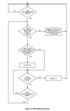
If you look at the MC145028P data sheet you will see a flow chart that shows it's operation (below).
You would write a program for the Pi to emulate that flow charge sequence.

You also need an RF receiver that converts the received RF signal to the digital pulses for input to the Pi.
You may be able hack a new garage opener to get the signal.

That's all a rather complex task if you haven't done anything like this before.

It likely would be a lot better and easier just to get new transmitters for all the trucks along with new receivers.
Transmitters aren't that expensive (less than $10 each on Amazon).
The new ones use a rolling code, which is much more difficult to clone then the old transmitters with a fixed code.
1683048369395.png
 
Last edited:

KA0IPN

May 2, 2023
8
Joined
May 2, 2023
Messages
8
Not a trivial task.

If you look at the MC145028P data sheet you will see a flow chart that shows it's operation (below).
You would write a program for the Pi to emulate that flow charge sequence.

You also need an RF receiver that converts the received RF signal to the digital pulses for input to the Pi.
You may be able hack a new garage opener to get the signal.

That's all a rather complex task if you haven't done anything like this before.

It likely would be a lot better and easier just to get new transmitters for all the trucks along with new receivers.
Transmitters aren't that expensive (less than $10 each on Amazon).
The new ones use a rolling code, which is much more difficult to clone then the old transmitters with a fixed code.
View attachment 58913
the problem with buying the new style is that every time a truck came to the door it would have to be programed for that door. multiple locations use the same board at the present time. the new ones wont work the way we want them to.
over 30 locations with from 3 to 6 doors. each of the doors are coded for the type of truck in use.
so presently all locations have door 1 programed the same, door 2 are the same... and so on.
as for the rf portion i do not see that as a problem for me. just the codes.. and to figure out how to do the open close and stop on each as well.
really cant be the new styles of door openers.
I understand why they make them that way but in this case it wont work.
 

crutschow

May 7, 2021
848
Joined
May 7, 2021
Messages
848
figure out how to do the open close and stop on each as well.
Isn't that normally intrinsic to the door opener circuitry, as it just takes a pulse to start up or down, and automatically stops at end of movement?
That's all the manual push-button on the wall does to control the door (at least for all the residential openers I've used).
So the output signal from the Pi when it detects a valid code, could just operate a small relay to close its contacts and simulate the button push.

I understand now why the new remotes won't work for your application.

I've never programmed a Pi but it would seem that the program to perform the algorithm of the flow chart would be fairly straight forward (have you done any programming?).
I would assume there would be an external set of dip switches that the Pi would read for the code (how many code switches do the transmitters have?).
 

kellys_eye

Jun 25, 2010
6,514
Joined
Jun 25, 2010
Messages
6,514
There are undoubtedly existing (new) systems that offer a tx/rx solution to the problem and probably easier to take the decoded output of the 'new' system to operate the 'last part' of the existing receive/open/close system. The MC145028 has an output pin (Vt) to indicate a correctly received code so find the 'output' of the new system and wire that into the (Vt) position and you have a working system based on the old mechanism.

Even car remotes can do this and it's possible to have them reprogrammed either identically or individually as required.
 

KA0IPN

May 2, 2023
8
Joined
May 2, 2023
Messages
8
Isn't that normally intrinsic to the door opener circuitry, as it just takes a pulse to start up or down, and automatically stops at end of movement?
That's all the manual push-button on the wall does to control the door (at least for all the residential openers I've used).
So the output signal from the Pi when it detects a valid code, could just operate a small relay to close its contacts and simulate the button push.

I understand now why the new remotes won't work for your application.

I've never programmed a Pi but it would seem that the program to perform the algorithm of the flow chart would be fairly straight forward (have you done any programming?).
I would assume there would be an external set of dip switches that the Pi would read for the code (how many code switches do the transmitters have?).
Mostly correct but .. there is also a stop on the ones we use.
the only thing i can not duplicate is the MC145028P and that is for the decoding of the binary and comparing it to the set code (dip switches)

as stated the new styles are programmable but that wont work. its not the remotes i have to duplicate. it is the decoding on the reciever board. and comparing it the set code.

need all door 1 receivers the same as an example. 30 to 40 remotes will need to access it. and need the stop because it is not a up down door. they are bi-folds.

lastly .. I have never used one of these boards before and just starting to look into them mostly for this project.

I appreciate your input.
 

crutschow

May 7, 2021
848
Joined
May 7, 2021
Messages
848
the only thing i can not duplicate is the MC145028P and that is for the decoding of the binary and comparing it to the set code (dip switches)
It would seem to be not too difficult to generate a program to perform the functions of the MC145028P flow chart in post #2.

Have you done any programming before?
If not, you may have to find someone who has, or take the time to learn the basics of programming.
The Basic language is one of the easiest to start with, using common English words for the commands, with versions that run on a Pi.
Other languages, such C and Python, tend to be more complex, cryptic, and difficult to understand and learn, and are overkill for this project.
Here is an example.
 
Last edited:

KA0IPN

May 2, 2023
8
Joined
May 2, 2023
Messages
8
The MC145028P has only one output so how does it discriminate between up, down, and stop?
I think it allows the other part of the circuit to use the signal.
and it turns out we are not the only ones having the issue. its across the country.. large cities with fire departments have to change the way they do their doors due to this.
 

KA0IPN

May 2, 2023
8
Joined
May 2, 2023
Messages
8
I think it allows the other part of the circuit to use the signal.
and it turns out we are not the only ones having the issue. its across the country.. large cities with fire departments have to change the way they do their doors due to this.
OK// uses the 10th line as in the dip switch has 9 pin but it uses the tenth line to do the work.
they are 3 position dip switches.. ground, open and High I believe.
 

KA0IPN

May 2, 2023
8
Joined
May 2, 2023
Messages
8
That makes no sense to me.

All the dip switches I've seen are binary with just two positions, giving a logic high or logic low output.
yes they are strange but they are made. center off position..
 

crutschow

May 7, 2021
848
Joined
May 7, 2021
Messages
848
the remote and the wall have a open, close, and a stop. commercial type setup
Then you need to determine exactly what the MC145028P decoder outputs for those three different signals, so you know what the Pi needs to generate.
All you have at this point, is speculation.
 
Top