Maker Pro
Maker Pro

Help diagnose Vinnfier sub woofer no power on

mikey5791

Jun 7, 2013
174
Joined
Jun 7, 2013
Messages
174
Hi,
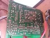
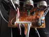
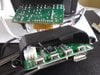
When i switched on ac power, there is no blue led power on. So i suspect something gone bad at the power board. Not able to search any schematic. Noticed a dual op amp 8 pin 4558d jrc 0058t, i googled and found vcc is pin 8 and ground is pin 4. Another set of 5 pin mosfet tda2030Al are audio power amp, power supply is pin 5 and ground is pin 3.
My question is can i safely use my dmm probe on the above pins to check for live voltage?
Hopefully i can detect some bad chip this way. Or perhaps someone kind enough to point me to the right way of diagnosing and checking safely.
Thank you in advance.
 

Attachments

  • IMG_20201013_111531.jpg
    IMG_20201013_111531.jpg
    228.3 KB · Views: 4
  • IMG_20201013_111929.jpg
    IMG_20201013_111929.jpg
    309.1 KB · Views: 4
  • IMG_20201013_112156.jpg
    IMG_20201013_112156.jpg
    239.1 KB · Views: 4
  • IMG_20201013_112242.jpg
    IMG_20201013_112242.jpg
    226.6 KB · Views: 4

73's de Edd

Aug 21, 2015
3,622
Joined
Aug 21, 2015
Messages
3,622
Sir mikety mike 5791 . . . .

You say . . . . . there is no blue led power on . . . . ..

Your second photo shows switched AC line power going to the primary of the units power transformer via heavy RED leads.
Bundled within that wiring cluster, with its white zip cable clamp, there seems to be a BLACK vinyl boot with a fuse inside.
See if its blown . . . . and if so . . . . . DON'T just pop in another fuse and power up and then just have it . . . . POP!
Ve are needink' to see vat is dun happenink, und vat ist causink dis !


73's de Edd . . . . .

Right now I'm having amnesia and deja vu at the same time . . . . . meaning . . . . . I think I've forgotten this before .

.
 
Last edited:

mikey5791

Jun 7, 2013
174
Joined
Jun 7, 2013
Messages
174
Hi 73's de Edd,
Thanks for your reply.
I checked the glass fuse F1.5AL using an analog multimeter and it has continuity and no sign of blown fuse. I am attaching the top and bottom photo of the board.
Fyi, i have a digital multimeter and a 40watt soldering iron with little soldering experience.
I am willing to learn how to diagnose and repair this sub woofer to working condition.
Look forward at your guidance and suggestion..
 

Attachments

  • IMG_20201014_084055.jpg
    IMG_20201014_084055.jpg
    215.9 KB · Views: 3
  • IMG_20201014_083344.jpg
    IMG_20201014_083344.jpg
    245.3 KB · Views: 2
  • IMG_20201014_083757.jpg
    IMG_20201014_083757.jpg
    255.3 KB · Views: 3

mikey5791

Jun 7, 2013
174
Joined
Jun 7, 2013
Messages
174
Hi,
Today i do some voltage testing.
Measured dcv on two large lytic caps, c32=18vdc and c31=18vdc (both caps are rated 4700uf 25v)
Measured op amp 4558, i got dcv reading 32vdc by using dmm red positive on pin 8 and black negative on pin 4. Not sure if these readings are within normal range.
 

mikey5791

Jun 7, 2013
174
Joined
Jun 7, 2013
Messages
174
More pictures on switch of volume,treble, bass,usb, sd connector top and bottom side.
Hope all this helps.
 

Attachments

  • IMG_20201016_091447.jpg
    IMG_20201016_091447.jpg
    240.2 KB · Views: 4
  • IMG_20201017_092207.jpg
    IMG_20201017_092207.jpg
    211.9 KB · Views: 7
  • IMG_20201017_092628.jpg
    IMG_20201017_092628.jpg
    280.3 KB · Views: 5

73's de Edd

Aug 21, 2015
3,622
Joined
Aug 21, 2015
Messages
3,622
Sir mikey5791 . . . .

Thank goodness for your final extra photos.
With ONLY the first set of photos I was wondering WHY the THREE power audio amplifiers .
In addition to the WOOFER / BASS speaker, it now seems that audio is additionally processed for two remoted, plug in satellite, right and left channel speakers.
The mentioned voltages all read within expected specs and with + 15 and - 15 both used for the 4558 dual amp.
So apparently there is need for a lower supply level for the rest of the system and that is being derived from tapping off of the +15 supply.
Considering that . . . . now look in your last series of photos . . .specifically at IMG_20201017_092207.jpg.
A POSSIBILITY ?
Denote the left front foreground . . . confirm if that is being a 3 terminal voltage regulator and that it suredly had a SNo + PBo oxide build up on ts leads
back at board stuffing of manufacturing time at re-flow soldering operation.
RESULT
That oxide depth kept its two bottom leads from receiving a FULL flow solder overflow, such as the top terrminal received.
The bottom two only only created a minimal re-flow melding of the solder and a SKIMPY, minimal area connection was made then.
Now has it has fractured and left a floating connection(s) ?
Confirm ?

73's de Edd . . . . .

The higher you go in the corporate structure, the smaller your balls become.
There must be a ton of people in Washington playing marbles!


.
 
Last edited:

mikey5791

Jun 7, 2013
174
Joined
Jun 7, 2013
Messages
174
Hi 73's de Edd,

Indeed Sir you have a sharp eye for detail. From your comment, i did a reflow on the three terminal voltage regulator ,and voila the sub woofer power led came back on ! (Noticed my solder work was not that great as in the attached picture) The great thing is It is now working fine as it is supposed to. Many thanks for your kind help.
 

Attachments

  • IMG_20201017_150346.jpg
    IMG_20201017_150346.jpg
    202.1 KB · Views: 7
Top