Maker Pro
Maker Pro

Help identifying a transistor

AndrewC

Jun 10, 2023
5
Joined
Jun 10, 2023
Messages
5
Hi,

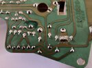
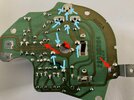
I am trying to diagnose what is wrong with a controller board for the wiper motor in my 1988 Corvette. Replacements aren't commercially available anymore, hence fixing rather than replacing.
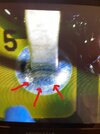
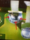
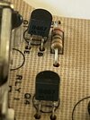
There are four transistors on the board marked '8467' and '727' with what looks like the Motorola logo. The rear of the TO-92 package has three lines painted on it, red, violet and yellow.
Google searches don't seem to turn anything up for these.

Firstly: Does anybody know what these are or what their equivalent is?

Secondly: I am assuming these are a BJT transistor, because the PCB has ECB markings for emitter, collector and base pins. I am assuming a TO-92 packaged MOSFET would not have these markings on the board, instead using SDG? The reason I ask is I attached a simple in-circuit transistor tester to them and it does not indicate a working NPN or PNP transistor. I suspect the probability of all four transistors being dead is low, hence the question about them being something else.

Sorry if these are dumb questions. I don't know that much about electronics.
Thanks in advance.
 

Attachments

  • IMG-1643.jpg
    IMG-1643.jpg
    230.7 KB · Views: 14
  • IMG-1642.jpg
    IMG-1642.jpg
    310.5 KB · Views: 13
  • IMG-1641.jpg
    IMG-1641.jpg
    271.1 KB · Views: 13

ivak245

Jun 11, 2021
108
Joined
Jun 11, 2021
Messages
108
Try putting "2N" before the numbers. Could also be a UJT in that lot as well. Have you tried getting a circuit diagram for this? You may find something on a Corvette forum.
 

Delta Prime

Jul 29, 2020
1,969
Joined
Jul 29, 2020
Messages
1,969
Sorry if these are dumb questions. I don't know that much about electronics.
No! not a dumb question.
General purpose audio frequency drivers
The data sheet is absolutely horrible. If you post a photo of that sweet 88 Corvette I'll get you a better one! ;)
 

Attachments

  • BC727.PDF
    141.4 KB · Views: 5
Last edited:

H2814D

Nov 4, 2017
215
Joined
Nov 4, 2017
Messages
215
If you aren't familiar with Chevrolet/GM Vehicles in that time period, and the issues they had with printed circuit boards and cold solder joints, today is the day. Take that board and turn it over. Take very clear photographs of the solder connections on that side and post them here.

You didn't mention what was wrong with your wipers, but if they are intermittent, won't shut off, won't come on, and possibly stay on longer than usual, then the probability of those broken solder connections is high. The problems affected the wipers, the anti-lock braking systems, and the radios, to name a few.
 

Bluejets

Oct 5, 2014
6,928
Joined
Oct 5, 2014
Messages
6,928
The reason I ask is I attached a simple in-circuit transistor tester to them and it does not indicate a working NPN or PNP transistor.
Mostly, testing is done with the device out of circuit otherwise one can get misleading results.
You don't say what the fault actually is either.
For further diagnosis, suggest a full photo of each side of the board.
 

AndrewC

Jun 10, 2023
5
Joined
Jun 10, 2023
Messages
5
If you aren't familiar with Chevrolet/GM Vehicles in that time period, and the issues they had with printed circuit boards and cold solder joints, today is the day. Take that board and turn it over. Take very clear photographs of the solder connections on that side and post them here.

You didn't mention what was wrong with your wipers, but if they are intermittent, won't shut off, won't come on, and possibly stay on longer than usual, then the probability of those broken solder connections is high. The problems affected the wipers, the anti-lock braking systems, and the radios, to name a few.
I have attached some photos. There was some obvious corrosion on the joins by the ground strap and the large pad to the left of it, which I've cleaned up a little.
The board -- as I understand it -- controls the intermittent function only. Normal high and low function goes directly to the motor and seems to work fine. When the board is installed, there is a plastic shaft that protrudes through the hole in the middle of the board and a plastic wheel with a ramp on one side is rotated by the motor and depresses the reed switch as the ramp rides over it.
 

Attachments

  • motor.jpg
    motor.jpg
    67.1 KB · Views: 12
  • wheel thingo.jpg
    wheel thingo.jpg
    13.1 KB · Views: 10
  • IMG-1650.jpg
    IMG-1650.jpg
    274.5 KB · Views: 12
  • IMG-1649.jpg
    IMG-1649.jpg
    339.1 KB · Views: 9
  • IMG-1648.jpg
    IMG-1648.jpg
    261.5 KB · Views: 11
  • IMG-1647.jpg
    IMG-1647.jpg
    232.8 KB · Views: 10
  • IMG-1646.jpg
    IMG-1646.jpg
    307.1 KB · Views: 10
  • IMG-1645.jpg
    IMG-1645.jpg
    300.9 KB · Views: 9

AndrewC

Jun 10, 2023
5
Joined
Jun 10, 2023
Messages
5
Mostly, testing is done with the device out of circuit otherwise one can get misleading results.
You don't say what the fault actually is either.
For further diagnosis, suggest a full photo of each side of the board.
Yes, I realise that's the most thorough way to test it. I'm not confident about desoldering things and putting them back (or their replacements) without damaging the board further. The transistor tester I used was just one of those simple astable oscillator kits connected to the transistor legs. Similarly I was hoping an ESR tester would suffice for the capacitors in-situ.
 

Delta Prime

Jul 29, 2020
1,969
Joined
Jul 29, 2020
Messages
1,969
It's the reason for in circuit transistor tester if it was working before properly it takes into account that transistor to amplify maybe that's why they put in AF amplifier transistors in there so you quickly check if they're dead or still operative . And you have done just that. Now the scary part.., you got to desolder them!!:eek:
By the way your method of troubleshooting is impressive and don't worry those traces and solder pads are robust and the transistors themselves are pennies on a dollar
 

kellys_eye

Jun 25, 2010
6,514
Joined
Jun 25, 2010
Messages
6,514
The most 'obvious' issue (to me) seems to be this area: the pins are clearly 'unconnected'. Desolder, clean and refit.
 

Attachments

  • Screenshot from 2023-06-10 09-25-10.png
    Screenshot from 2023-06-10 09-25-10.png
    331.7 KB · Views: 8

Delta Prime

Jul 29, 2020
1,969
Joined
Jul 29, 2020
Messages
1,969
An additional photos needed I would like to see the underside of that blue thingy and as is. Focusing on the solder connections please.1686387794990.jpg

If you're really unsure about your soldering perhaps a friend could help you.


Delta Prime

Jul 29, 2020
1,969
Joined
Jul 29, 2020
Messages
1,969
Could be a game of lights and shadows further inspection is needed by you of course the teeth look rounded but why just at that point they should all be rounded.
photo_1686388615683.png
 

AndrewC

Jun 10, 2023
5
Joined
Jun 10, 2023
Messages
5
Could be a game of lights and shadows further inspection is needed by you of course the teeth look rounded but why just at that point they should all be rounded.
View attachment 59456
Thanks for the posts. I'll check out the board issues you've flagged and follow up in the next couple of days.
The picture of the motor and the blue wheel were just grabbed from google as I don't have the originals to hand at the moment. Those teeth on the white motor gear are helical, which is probably why it looks a bit funny.
 

Delta Prime

Jul 29, 2020
1,969
Joined
Jul 29, 2020
Messages
1,969
I'm not a mechanical engineer but I played one on a television show.:p
 
Last edited:

H2814D

Nov 4, 2017
215
Joined
Nov 4, 2017
Messages
215
Yes, I realise that's the most thorough way to test it. I'm not confident about desoldering things and putting them back (or their replacements) without damaging the board further. The transistor tester I used was just one of those simple astable oscillator kits connected to the transistor legs. Similarly I was hoping an ESR tester would suffice for the capacitors in-situ.
Where Delta Prime and Kellys_eye have pointed out the cold/broken solder joints, you simply need to heat up your solder gun high enough to melt that solder. Add a bit more solder to each one of them until the solder corrects the bad joints. There is another one that is visible in Delta Prime's altered photo just below the shaft of the arrow pointing to the upper left, the furthest left arrow. He may have just misaligned that arrow. I added a bunch more blue arrows (not as pretty as Delta's :)) that should be redone too, just to make sure you get all of them. See that pic (Delta's red arrows and my blue-ugly-arrows).

Bad solder joints, magnified, look like these. They are hard to see unless magnified somewhat, unless you know what you are looking for. These pics aren't of yours, but will give you an idea as to what to look for. Don't do anything else to that board as far as trying to test or remove anything. Reflow those solder joints first, put the board back in the car, and then enjoy the fix you just accomplished.

I just looked at the top part of your board again too, the component side, and may see one more. Where the board says "Reed ASM" there appears to be one more solder joint that may need to be looked at closely.

Good luck. Make sure you come back and let us know how it went please.
 

Attachments

  • Inkedphoto_1686387148119.jpg
    Inkedphoto_1686387148119.jpg
    555.8 KB · Views: 7
  • InkedIMG_9508.jpg
    InkedIMG_9508.jpg
    314.6 KB · Views: 7
  • InkedIMG_9509.jpg
    InkedIMG_9509.jpg
    458 KB · Views: 5
  • InkedIMG_9511.jpg
    InkedIMG_9511.jpg
    470.1 KB · Views: 7
Last edited:
Top