Maker Pro
Maker Pro

Help Me/ hook up a forward-stop-reverse motor cont switch on a 220volt mill machine

sea

Mar 28, 2012
30
Joined
Mar 28, 2012
Messages
30
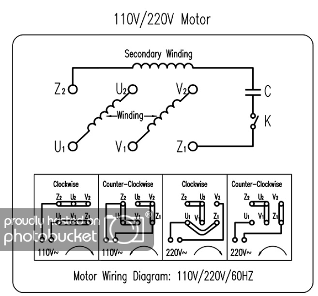
I have a bad switch on my machine and was given this new switch by a dealer of these milling machines, but its very different looking in the way its hooked up than the one on my machine

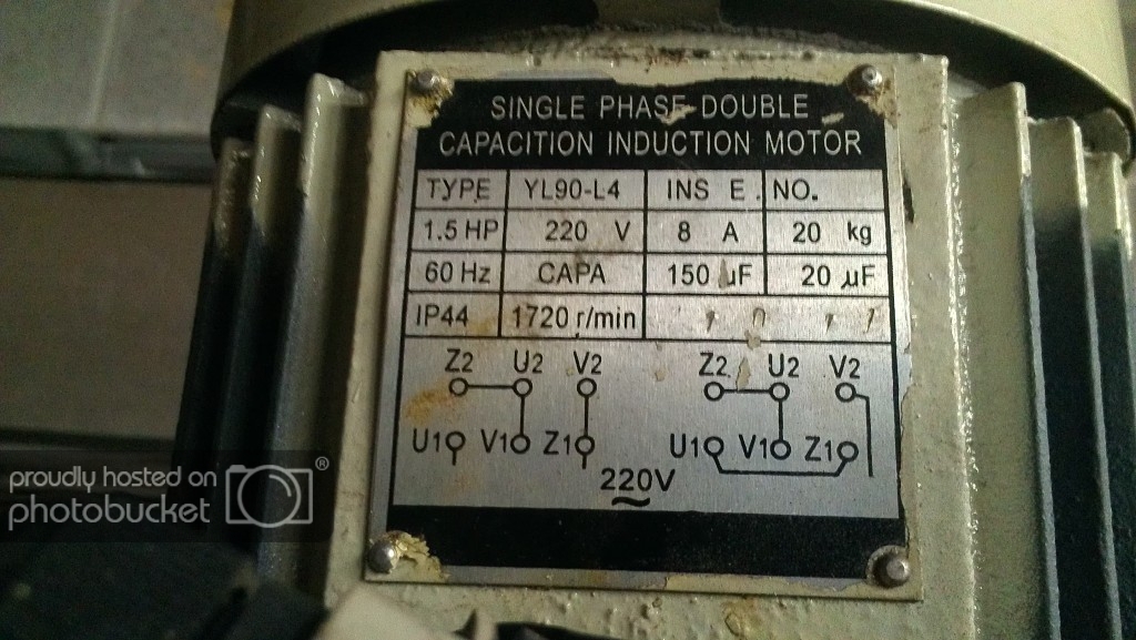
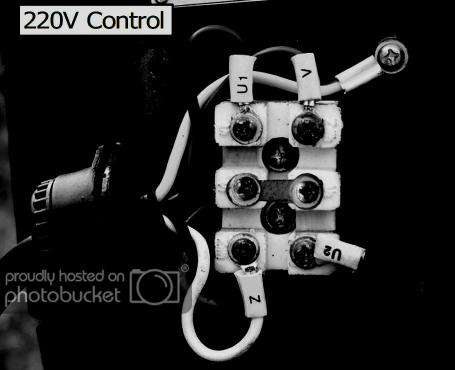
Machine is a 220 volt 1-1/2 hp milling machine (for milling down metals)

What I need to know is where to put the wires on the switch to make it work

Machine needs to go in: Forward - Stop - Reverse

I have the 2 power wires that need to be hooked into switch the ones coming from the outlet (2 hot wires)


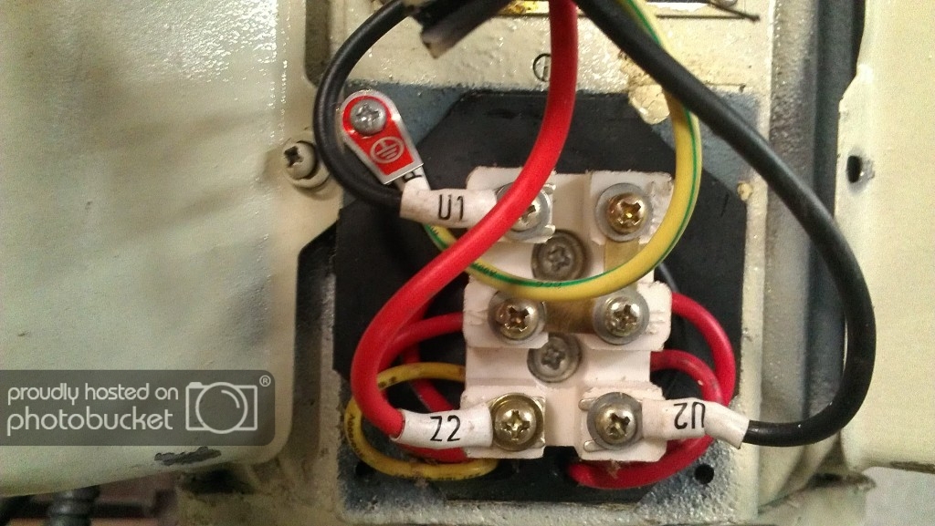
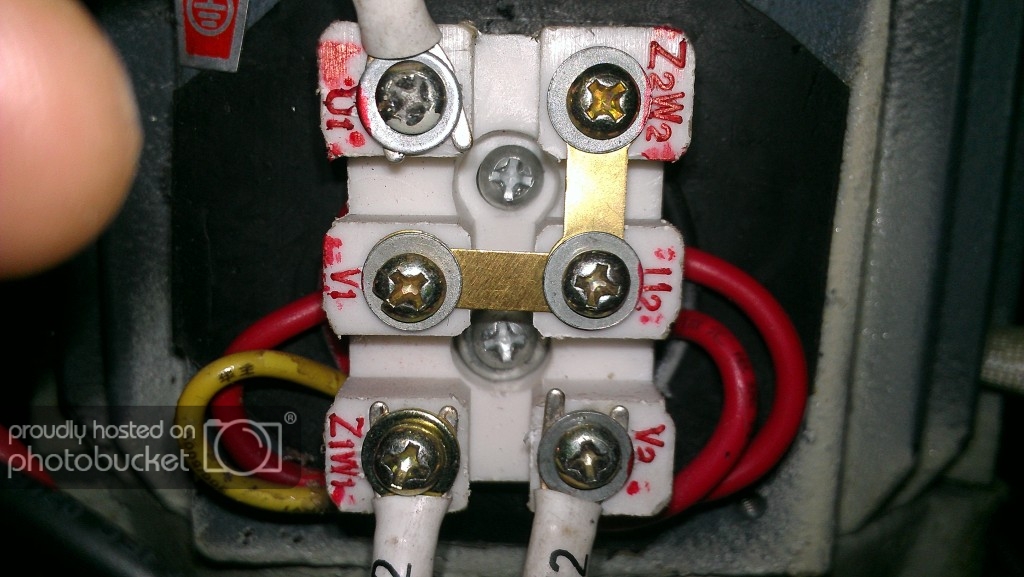
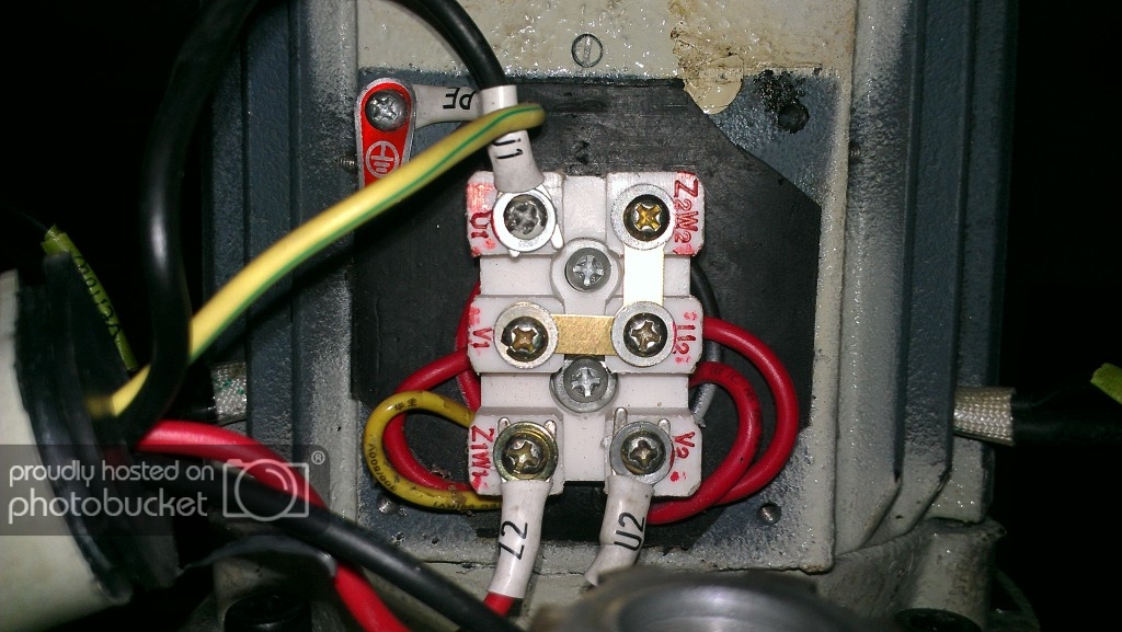
Then out of the switch I have 3 wires going straight to motor, they are:

Black wire labeled - U1

Black wire labeled - U2

Red wire labeled - Z2 (which I am guess make the motor reverse)

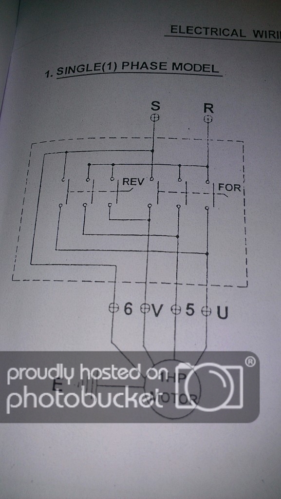
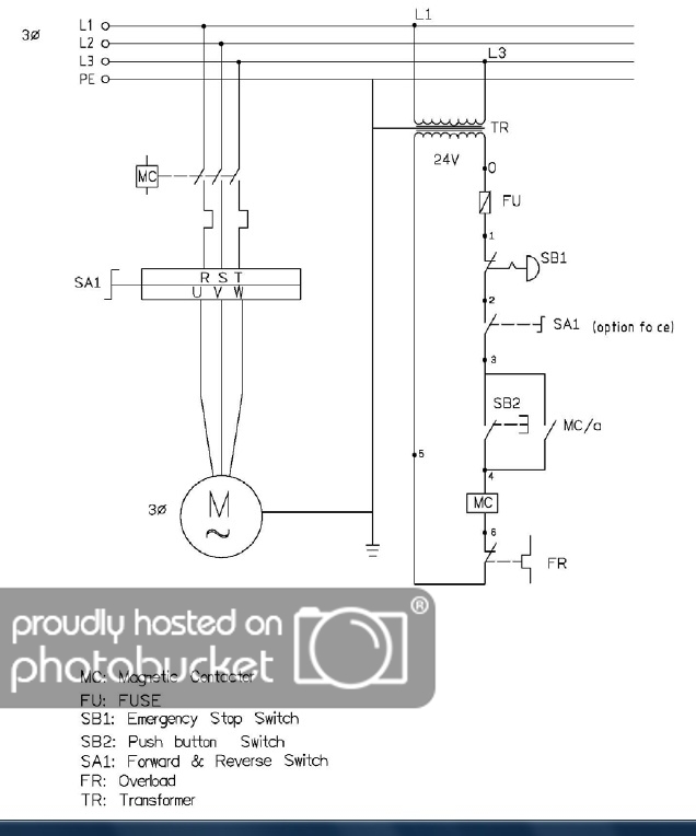
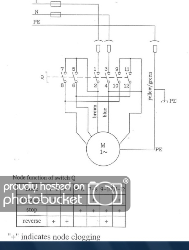
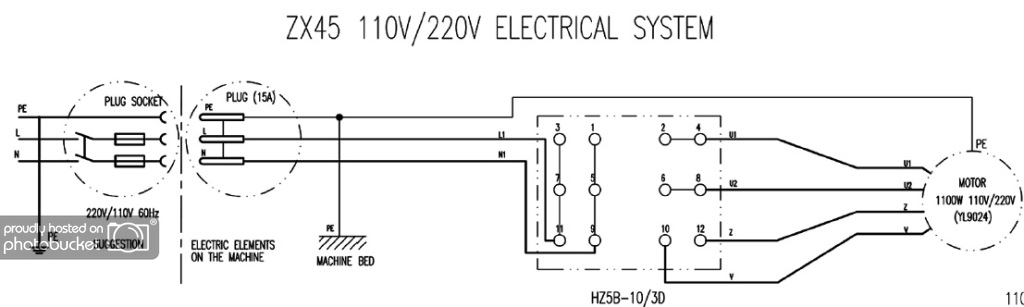
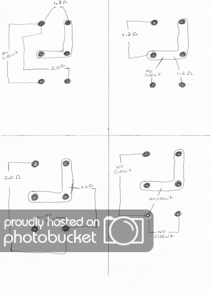
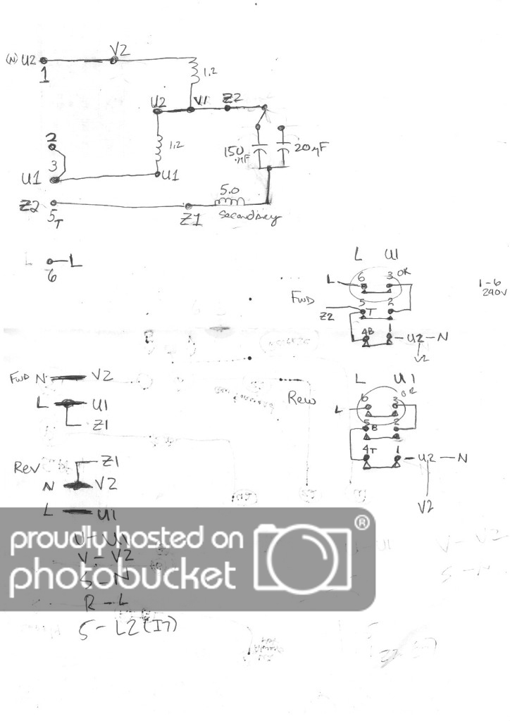
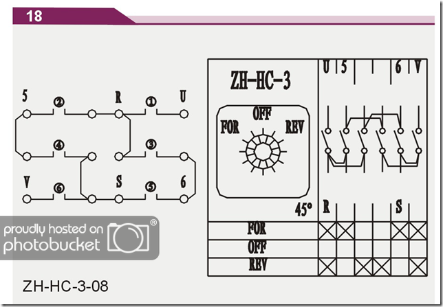
Picture of schematic of switch that needs to be put in

switch.png
 

john monks

Mar 9, 2012
685
Joined
Mar 9, 2012
Messages
685
Not enough information.
Do you have the make and model number of the milling machine?
Do you have the part number or any number from both switches?
You might have to get the old switch working well enough to ohm it out and match up the new switch pin by pin.
 

sea

Mar 28, 2012
30
Joined
Mar 28, 2012
Messages
30
The old switch has no markings and the some of the contacts fell out and its not in time anymore with where its supposed to be since the limiting cog fell out that limited the switch to 45 degree's and it spun and that can be put back in several different ways, so a meter on it wont work since its not anywhere as it was when working.

Picture on front of motor ... make/model of machine unknown

IMAG0069-2.jpg


Motor terminal block just under plate above

IMAG0042.jpg
 

john monks

Mar 9, 2012
685
Joined
Mar 9, 2012
Messages
685
Now things are clear.
When the switch is in forward U is connected to R, 5 is connected to R, V is connected to S, and 6 is connected to S.

When the switch is in reverse U is connected to S, 5 is connected to R, V is connected to S, and 6 is connected to S.

The R and S are the 220 VAC line.
The U, 5, V, 6 are marked on the terminal block just under the plate on the motor.

You still may have to ohm out your new switch.

I hope work on this with it unplugged from the wall.
 
Last edited:

sea

Mar 28, 2012
30
Joined
Mar 28, 2012
Messages
30
I got slightly different readings with a meter on the switch as to your reverse connections:

Here's what I metered new switch at:

Forward: S – connects to .....6 & V
R- connects to ..... 5 & U

Reverse: S- connects to ...... 5 & V
R- connects to ...... 6 & U

Off: does not connect S or R to anything

Now I have 2 power wires coming in from AC outlet I was told that ( S and R ) are the proper connections for those


Then I would need 3 connections coming out of switch, going up to motor can you figure it out by looking? I am sure this all makes sense but my head can't get wrapped around it right now lol

I have ------ U1 (black wire for forward)
U2 (black wire for reverse)
Z2 (red wire this is the common wire that is used for forward and reverse, this is the wire that needs to be powered up when either in forward or reverse)

Too me it looks like I need to take some of the removable jumpers out the ones that run to middle of switch next to 5, U, 6, or the one left of S


Thanks for your help so far its really appreciated I assure you
 
Last edited:

john monks

Mar 9, 2012
685
Joined
Mar 9, 2012
Messages
685
Looks like you're in luck.
The only discrepancy is that your S and R are reversed in the reverse direction from what I got. That makes no difference to the motor.
This also may explain why the manufacturer went with a different switch, that is to keep the hot line, S, from being applied to the motor when the switch is in the OFF position.
So hook it up and see what happens after you plug it in...
 

sea

Mar 28, 2012
30
Joined
Mar 28, 2012
Messages
30
So I ended up using a meter to get the switch so no wires would co-mingle when the switch was used

Forward: sends power via Z2 and U1 up to the motor

Off: no lugs are hot on switch (none of the ones I have U1, U2 or Z2 hooked to)

Reverse: sends power via Z2 and U2 up to the motor

This did not work, obviously this is not the way this motor is supposed to be hooked up as I had thought

Noticed one thing on old switch that could be seen from outside even though the old switch is screwed up, one of the power wires coming from the wall is always hot and can never be turned off its U2, I noticed this because it has a jumper right on the old switch straight to constant power .. its connected right to one of the hot wires that come from the outlet, so that tells me my theory that U2 shoud be used for Reverse only is not the case

I figured out how this switch can be made to whatever I want but the 3 hot wires going to motor now I don't know exactly when they are to be off on or constantly on

Can you tell that from the schematic on the motor plate??

One other note from when I replaced the capacitors (I got the same values as was there from factory), the Run capacitor is rated at 440 volts/ 20 UF and the Start capacitor was rated at 220 volts 150UF, maybe that means something as well I am not very versed in such things
 
Last edited:

john monks

Mar 9, 2012
685
Joined
Mar 9, 2012
Messages
685
Hate to put you through all this trouble but it seems that I don't have enough information.
You may have to disconnect everything connected to the terminal block and ohm out what you have. I believe you may have three separate windings in the motor. Two for running and one as a magnetic brake.
As I see it, when running, one winding is connected to the main and another is connected in series with the small capacitor to the main. And for starting the large capacitor is connected in parallel with the small capacitor and disconnect by an internal switch from the motor when the motor gains sufficient speed.
Now for reverse running the windings are simply switched one for the other, or one winding is simply reversed.
The third winding, the magnetic switch is not connected except when the motor is switched off. In that case the ends of the windings are shorted together.

When you ohm this out I expect two of the windings to measure a near dead short, something less than one ohm. And one winding to measure something different, maybe higher.

This is a lot of trouble but short of coming up with the exact make and model of the motor I think we're stuck.

Unfortunately what you discovered so far does not match up with what's on the plate. That's why I can't answer your question.
 

sea

Mar 28, 2012
30
Joined
Mar 28, 2012
Messages
30
Hello, yeah I hear a centrifugal switch once you turn motor off that I hear click when it was running also I think you are on to something about this magnetic switch, I found a few diagrams of very similar machines, they have other safety switches on them and what not but its the same motor, I am not home today to get that meter out so i figured I would post these pic's I found

rf45.jpg


rf451.jpg
 

john monks

Mar 9, 2012
685
Joined
Mar 9, 2012
Messages
685
Is your machine a Grizzly model G3102?
There is an owner's manual online.
 

sea

Mar 28, 2012
30
Joined
Mar 28, 2012
Messages
30
No mine is a clone of a RF45 (Rong Fu 45) ... its a PM45 the problem is they are all wired differently

Mine is second on this list, but no wiring diagrams for it exsist, these are all basically the same exact machine in looks, I pulled those 2 diagrams from a few of these machines

YL90-L4 is the motor model as seen in the picture of the motor plate, this from what i can tell is a heavily used motor on tons of these machines

http://www.hossmachine.info/images/Hoss RF-45 Mill Comparisons.jpg

Notice page 9 on this pdf, this looks exact same as mine but the problem is this one uses one more wire going to motor block

http://www.boltonhardware.com/images/pdf/zx45.pdf
 
Last edited:

sea

Mar 28, 2012
30
Joined
Mar 28, 2012
Messages
30
Here's a picture of my motor, there are raised labels next to the lugs on the motor, I just dragged a red marker over them so they could be seen.

IMAG0092.jpg


IMAG0093.jpg
 

sea

Mar 28, 2012
30
Joined
Mar 28, 2012
Messages
30
Here's some pictures from the above PDF of that other mill, the one with 1 more wire to make it easier for you to look at rather than going to PDF file above, the motor block looks like its identically labeled, I played with the contrast on it to make it easier to see the lug labels

220v-1.jpg


Other mill wiring motor diagram from above PDF

220v1.jpg


Switch schemtaic from other mills PDF

220v2.jpg
 
Last edited:

sea

Mar 28, 2012
30
Joined
Mar 28, 2012
Messages
30
Below is motor lug box in same orientation as above pictures

Tested with meter set to: 200 ohm setting

All wires are removed from motor lugs for this testing

As you will see below there are only 3 results, they are either: 2.0 ohms, 1.2 ohms or No Circuit

motortest.jpg
 

john monks

Mar 9, 2012
685
Joined
Mar 9, 2012
Messages
685
Your in luck.
You have two stator windings. One between U1 and V1 and another between U2 and V2.
V1 and U2 are lugged together for 220VAC operation.
Each winding is designed for 110VAC operation.
They can be connected in series for 220VAC operation as in your case.

There is another circuit, a coil and some capacitance that is connected to Z1 and Z2.
This circuit is designed to run off 110VAC. This is done by connected it in parallel with one of the stator windings.
The direction the motor turns is controlled by the phase of the 110VAC that is applied to Z!W1 and Z2W2.
In your case Z2W2 is connected to V1. And Z1W1 goes to your forward/reverse switch. This connects it either to U1 or V2, U1 for one direction and V2 for the other direction.

So what you want to check for is that your line cord connects directly to U1 and V2, and that Z1W1 is conned to U1 or V2.
If this checks then the next thing to do is plug the machine in and see if it works.

If you have 220VAC across U1 and V2 and Z1W1 is at the same potential as U! or V2 and the motor doesn't turn then something is wrong with the motor. This is unlikely because the numbers you gave back seem reasonable.
 
Last edited:

sea

Mar 28, 2012
30
Joined
Mar 28, 2012
Messages
30
Could you clarify just a bit for me to understand better? It gets confusing for me

Earlier today I did try another method

One hot direct from outlet, direct to U2(named wire) / V2( named lug) (this was what I found on old switch, it was jumped on the switch in such a way as to never turn off power to this lug, no matter where the switch selector was put)

The other hot from outlet to switch to motor:

Switched Off: Off

Switched Forward: Live/Hot Z2 (named wire) / Z1W1 (named motor lug)

Switched Reverse: Live/Hot U1 (named wire) / U1 (named lug)

My results from above were:

Select Reverse on switch:
Very slow or or high wine coming from motor, would not get up to any speed at all even if I helped it along by hand, but did have some movement (seemed like it was confused as to what direction it needed to be going).

Select Off: Nothing, was off

Select Forward on switch:
Nothing much, maybe a very very faint hum if you got right up on the capacitors, but never a hint of any movement

My thoughts are I now know that motor was originally hooked to have U2 wire/V2 motor lug live at all times even when switch was off, so i went by that for the latest hook-up

Can you tell me exactly what wire or lug, whichever you would like should be switched, is it my above method?
 

john monks

Mar 9, 2012
685
Joined
Mar 9, 2012
Messages
685
So now you need to take some electrical measurements with the power on.

You need the voltage:
between U1 and U2. Should be 110 VAC.
Between V1 and V2. Should be 110 VAC.
Between U1 and V2. Should be 220 VAC.
Between Z1 and Z2. Should be 110 VAC.

Make sure your voltmeter is set for 220 VAC or more.

I suspect that either your starting circuit between is not getting power(Z1 and Z2) or your stator is not getting power (the other pins).
There is a chance something is wrong with the starting circuit.
 
Last edited:

sea

Mar 28, 2012
30
Joined
Mar 28, 2012
Messages
30
I had an electrical engineer come over and hook this up, it now works as before, he did note that the centrifugal switch never allows the start capacitor to work kick in, which is why I had to give the spindle a flick to get it to spin at full speed most of the time even before the switch went bad, its starting only on the run cap side.

But I am happy to say the new switch is in and works as before, thanks for all your help John I really appreciate everything you did.

He left this diagram behind I figured I would post it in case this could help someone else in the future.

switchmotor.jpg
 

CDRIVE

Hauling 10' pipe on a Trek Shift3
May 8, 2012
4,960
Joined
May 8, 2012
Messages
4,960
I had an electrical engineer come over and hook this up, it now works as before, he did note that the centrifugal switch never allows the start capacitor to work kick in, which is why I had to give the spindle a flick to get it to spin at full speed most of the time even before the switch went bad, its starting only on the run cap side.

Please rephrase this statement as I'm not sure what you're saying. I will tell you what I know to be true about Split Phase Capacitor Start/Capacitor Run Induction motors. I have a 1954 Logan 920 Lathe and a 1966 South Bend Heavy 10.

(1) The Start winding along with its series connected start capacitor are switched out of the circuit by the centrifugal switch when the motor RPM reaches about 65% of run speed.
(2) The Run Cap is connected in series with the Run windings and is never switched out of the circuit.
(3) The direction of rotation is determined by the Start winding's phase relationship to the Run winding only at Startup. Once the motor is running at > 65% of speed the Start winding and series Start cap are switched out by the centrifugal switch and has no effect any longer. If You quickly switch the motor from forward to reverse nothing should happen. It won't change direction unless the motor RPM fell below the centrifugal switch's dropout speed.
(4) If the Start winding is disconnected and you power the motor it should hum loudly until you manually spin the Stator shaft. It will run in either direction depending on which direction you spun it.
(5) If the motor will not run without manually spinning it by hand then either the Start winding, Start Cap or Centrifugal switch is bad or not wired correctly. The Start cap fails (leaky) far more often than Start windings or centrifugal switches fail.

(6) The wiring diagrams always seem to be more complicated than they need to be! :D
 
Top