Maker Pro
Maker Pro

Help on aquarium project

JohnZT

May 5, 2017
7
Joined
May 5, 2017
Messages
7
Hi all,

I am a beginner in this world and would like support in developing a project that I have in mind and what I will explain.

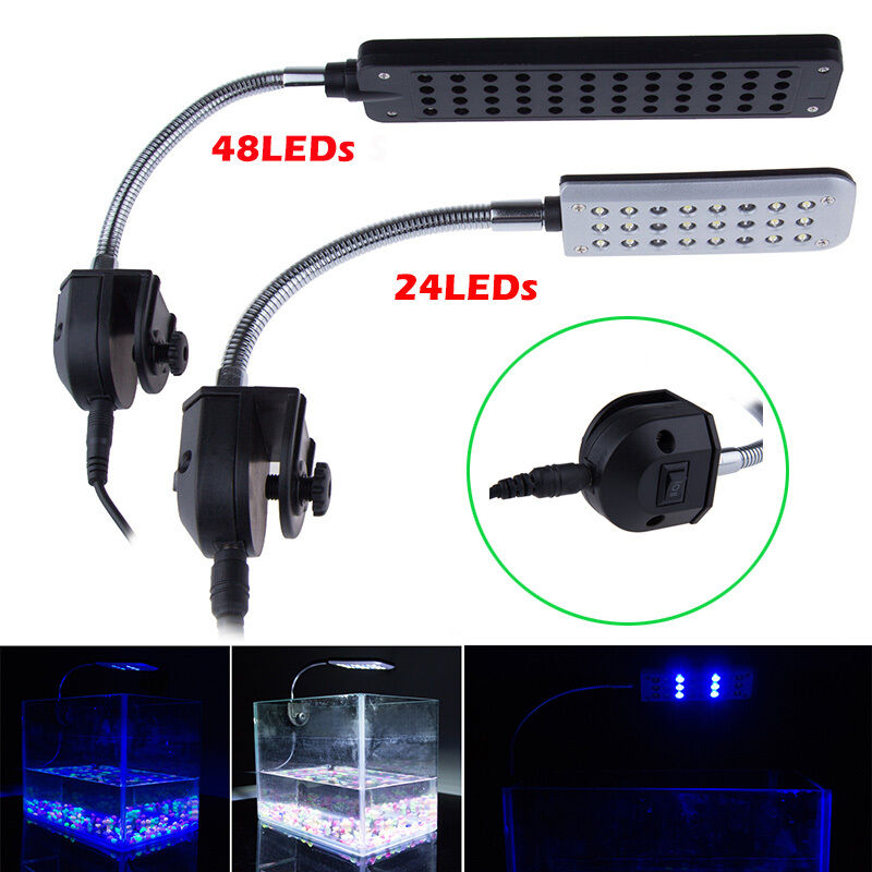
I want to replace the normal 12v aquarium led switch ON(Blue + White) – OFF – (Blue) into a light sensor system. Imagine ON(Blue + White) during the morning until there is enough light, OFF during the day and ON(Blue) during the night. Can you help me out on building a diagram and what to buy in order to setup this project?

Best regards
 

AnalogKid

Jun 10, 2015
2,892
Joined
Jun 10, 2015
Messages
2,892
A light sensor circuit with two outputs and a little logic is not difficult. Making it work in your application needs more information.

Where is the switch located with respect to the lights and the 12 V power supply?
Is the supply 12 V DC?
Does the switch go to a dimming controller?
If this is a lid or bar with the lights built-in and a switch on the front, you'll have to open it up for some minor surgery. What is your skill set for this?

ak
 

JohnZT

May 5, 2017
7
Joined
May 5, 2017
Messages
7
A light sensor circuit with two outputs and a little logic is not difficult. Making it work in your application needs more information.

Where is the switch located with respect to the lights and the 12 V power supply?
Is the supply 12 V DC?
Does the switch go to a dimming controller?
If this is a lid or bar with the lights built-in and a switch on the front, you'll have to open it up for some minor surgery. What is your skill set for this?

ak

Hi ak,

Thanks for the the quick reply,

This is the led that I have:
s-l1600.jpg


This led lamp is a 12v dc.
My intention is to use the top of the lamp to acomodate the new logic board and the LDR to control the system.
I am very confortable to disassemble and make the necessary changes, however I don't know what controllers should I use.

Thanks and regards
 

AnalogKid

Jun 10, 2015
2,892
Joined
Jun 10, 2015
Messages
2,892
It looks like a 3-position switch. Yes?
It looks like the 12 V source plugs into the bottom of the switch/mounting module. Yes?

If yes, yes, then there are a couple of ways to approach this. With the circuit mounted on the back (top side) of the light assembly, wires can run down the gooseneck and into the switch module. Or you can go directly into the light assembly, and leave the switch module untouched as a simple on/off device. Either way, the light sensor has to be somewhere where it will not be fooled by the aquarium lights it is controlling. One way to do this is to remote the sensor on a few feet of wire.

ak
 

JohnZT

May 5, 2017
7
Joined
May 5, 2017
Messages
7
It looks like a 3-position switch. Yes?
It looks like the 12 V source plugs into the bottom of the switch/mounting module. Yes?

If yes, yes, then there are a couple of ways to approach this. With the circuit mounted on the back (top side) of the light assembly, wires can run down the gooseneck and into the switch module. Or you can go directly into the light assembly, and leave the switch module untouched as a simple on/off device. Either way, the light sensor has to be somewhere where it will not be fooled by the aquarium lights it is controlling. One way to do this is to remote the sensor on a few feet of wire.

ak

Hi again AK,

Yes and Yes. The idea is to drill a hole on the top lamp platform to accommodate the ldr. The rest of the circuit can be near the switch. Can you point me out what do I need to buy? And help me with a diagram?

Thanks!
 

AnalogKid

Jun 10, 2015
2,892
Joined
Jun 10, 2015
Messages
2,892
What is the output current rating on the power supply. This gives a clue to the kind of switch part to use.

ak
 

AnalogKid

Jun 10, 2015
2,892
Joined
Jun 10, 2015
Messages
2,892
A simple light sensor circuit is, well, simple. It doesn't know the difference between faint morning light and faint evening light. With one sensor and two comparators, a full cycle would go like this:

night - blue
morning - blue + white
day - off
evening - blue + white
night - blue

Preliminary parts list:
1 - LM358 dual opamp
2 - power MOSFETs
1 - LDR (light dependent resistor
misc. resistors and capacitors

Unlike a comparator with an open-collector output, an opamp output can drive a MOSFET gate directly without needing a pull up resistor. The two MOSFETs are in series, forming a combo AND gate.

What kinds of electronic components do you have access to, and what is your experience with wiring a small circuit on perf board?

ak
 

JohnZT

May 5, 2017
7
Joined
May 5, 2017
Messages
7
Hi Ak,

I'm relatively comfortable doing small repairs with welding on circuit boards, regarding access to components I usually buy them on Ebay or if I'm in a hurry I usually buy some equipment at a local store.

Can I order the list above?

Best regards,
 

AnalogKid

Jun 10, 2015
2,892
Joined
Jun 10, 2015
Messages
2,892
Best to wait until you have a viable schematic. I'll work on one later today.

ak
 
Top